Difference between revisions of "Argon user guide/Braking resistor"
| [checked revision] | [checked revision] |
| Line 1: | Line 1: | ||
| − | {{ArgonManualNav}} | + | {{ArgonManualNav}}{{:Regenerative resistor}} |
| − | + | ||
| − | + | ||
Argon supports connecting braking resistor directly to drive [[Argon_wiring#J3_24V_power_and_motor_brake_port|J4 connector]]. | Argon supports connecting braking resistor directly to drive [[Argon_wiring#J3_24V_power_and_motor_brake_port|J4 connector]]. | ||
| − | |||
| − | |||
==Suitable resistor type== | ==Suitable resistor type== | ||
Revision as of 13:10, 30 March 2015
Regenerative resistors are usually a part with servo systems to absorb returned energy from decelerating or braking servo axis.
Servo drive with motor can act two ways: energy supply and energy generator. The generator behavior occurs during decelerations and this causes current flow from motor to drive power supply capacitors. If that generated energy is not absorbed anywhere, the voltage of capacitors will rise above overvoltage threshold and trigger an software clearable overvoltage fault.
| In most installations braking resistor is not needed at all. Resistor is needed in cases where fast moving motor with high inertial load is stopped rapidly causing conversion of the kinetic energy into electric current which needs to be dissipated by a resistor. Experimenting without resistor is safe as drive's overvoltage protection will prevent any damage occurring. If drive faults to overvoltage fault during deceleration, then try adjusting Over voltage fault thresholdFOV to higher value or add a braking resistor. |
Overvoltage faults
Scenarios where returned energy is causing the rise of HV DC bus voltage:
- Deceleration of motor speed when there is significant amount of energy stored in mechanical motion (rotating inertia or moving mass). This typically occurs with spindles and linear axes.
- Sudden reversal of torque setpoint. This can generate voltage spike even when motor is standing still. This typically occurs in high bandwidth torque control applications (such as Force feedback system (FFB)). These spikes are very short and an added capacitor to HV DC bus and/or low resistance regenerative resistor can provide a solution.
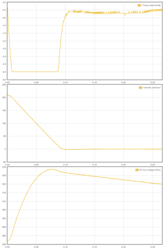
Voltage generation during deceleration of motor (motor current is negative, current is pumped to HV DC bus causing a 40 VDC rise).
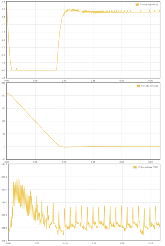
Voltage generation during deceleration of motor (motor current is negative, current is pumped to HV DC bus). However, in this case drive is equipped with regenerative resistor and tightly set Over voltage fault thresholdFOV parameter which prevents the significant voltage rise (only 5 VDC rise).
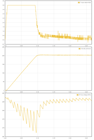
Example of accelerating motor (motor current is positive, power is drawn from HV DC bus which is causing a temporary voltage drop). Rectified 50 Hz mains AC ripple is easily seen in the voltage graph.


See also
- Overvoltage and undervoltage faults - practical guide for sizing regenerative resistor
Argon supports connecting braking resistor directly to drive J4 connector.
Suitable resistor type
Characteristics of Argon regenerative resistor output:
| Property | Value | Units |
|---|---|---|
| Maximum current | 6 | A |
| Series fuse | 8 | A |
| Minimum allowed resistance @ 230 VAC supply | 63 | Ω |
| Minimum allowed resistance @ 115 VAC supply | 35 | Ω |
| Resistor power dissipation | 0-2400¹ | W |
¹) Power dissipation depends on how much system's kinetic energy is directed to the resistor
Recommended resistor specifications:
- Resistance 80-100 ohms @ 220-240 VAC
- Resistance 40-50 ohms @ 110-120 VAC
- Power rating 150-300 Watts, this may greatly vary depending on how much energy the braking resistor must absorb
- Wire wound construction (no film resistors unless high peak energy capable)
- Preferrable in metal housing for grounding/noise shielding
The 250W resistor in the image can absorb enough peak energy to stop 100 kg mechanical linear axis moving up to 3 m/s.
Example of suitable resistor for most 220-240 VAC installations: Tyco HSC 250 82R (data sheet pdf).
Installation

The image aside shows proper wiring of braking resistor. Proper installation has:
- Shielded cable with 3 conductors with wire gauge at least 0.75 mm² / 18 AWG
- Cable shield AND earth conductor connected to drive PE terminal
- Earth conductor connected to resistor casing. Place toothed locking washers between wire terminal and resistor to break the insulating coating of resistor case.
- Two other conductors connected to resistor terminals through 8A fast blow fuse
- Resistor should be also mounted on heat sink
- Additionally it is a recommended to shield the resistor terminals from accidental touching
Parameterization
The important parameter that controls usage of resistor in Granity is the over voltage level FOV. Drive starts conducting current through resistor when HV DC bus voltage is near FOV value. It is important to set FOV high enough to prevent drive from using resistor constantly while AC supply is connected to the drive. The formula for mimimum FOV value is: FOVminimum=VAC*1.6. I.e. on nominal 230 VAC bus the FOV value should be set to no less than 368 VDC.
| Setting FOV value too low causes drive to use resistor constantly thus causing constant heating of resistor. Resistor easily overheats and burns in such case. After setting FOV, monitor resistor temperature for a minute in normal use to ensure that it is not over heating. |
Resistor sharing
It is possible to share HV DC link between Argon drives to reduce number of braking resistors needed. Sharing DC bus also forms a higher power HV DC supply between the drives allowing higher power drawn from a single drive if other drives are running on lighter load.

| The terminals of the resistors are connected to dangerous voltages. Never touch them before drive power has been safely discharged. |