Difference between revisions of "Tuning position controller"
| [checked revision] | [checked revision] |
(→Preparations) |
(edit text after param template) |
||
| Line 14: | Line 14: | ||
**Choose ''Serial only'' setpoint input {{param|CM}} | **Choose ''Serial only'' setpoint input {{param|CM}} | ||
**Make other necessary adjustments to have drive powered and enabled | **Make other necessary adjustments to have drive powered and enabled | ||
| − | **Untick | + | **Untick {{param|CIS}} |
**Set Goals tab {{param|DIV}} and {{param|MUL}} to 50 | **Set Goals tab {{param|DIV}} and {{param|MUL}} to 50 | ||
| − | **Set | + | **Set {{param|CAL}} & {{param|CVL}} limits reasonably to the levels that motor is expected to handle |
*Set-up the test stimulus and capture settings from Testing tab (an example, may be varied): | *Set-up the test stimulus and capture settings from Testing tab (an example, may be varied): | ||
**Set target setpoint 1 [[TSP1]] to 100 | **Set target setpoint 1 [[TSP1]] to 100 | ||
| Line 22: | Line 22: | ||
**Set target setpoint 2 [[TSP2]] to -100 | **Set target setpoint 2 [[TSP2]] to -100 | ||
**Set delay1 [[TSD2]] to 0.25 s | **Set delay1 [[TSD2]] to 0.25 s | ||
| − | **Choose | + | **Choose {{param|TSR}} of 500 to 2500 Hz |
**Choose ''Capture setpoint change in positive direction'' from the dropdown | **Choose ''Capture setpoint change in positive direction'' from the dropdown | ||
**''Tick Continuously repeating capture'' | **''Tick Continuously repeating capture'' | ||
**Tick ''Position setpoint'' and ''Position achieved'' from signals | **Tick ''Position setpoint'' and ''Position achieved'' from signals | ||
**Tick ''Start capture'' to begin continous capture. | **Tick ''Start capture'' to begin continous capture. | ||
| − | **Tick | + | **Tick {{param|TSE}} to begin a continuous position back and forth motion generation |
Once the steps above are done, motor should be generating short distance back and forth motion motion and position response graphs should appear on the right side of Granity about once in 3-5 seconds. | Once the steps above are done, motor should be generating short distance back and forth motion motion and position response graphs should appear on the right side of Granity about once in 3-5 seconds. | ||
| Line 67: | Line 67: | ||
[[File:posgains7.png|800px|]] | [[File:posgains7.png|800px|]] | ||
| − | Finally after playing little bit with all of {{param|KVP}}, {{param|KVI}} and {{param|KPP}} | + | Finally after playing little bit with all of {{param|KVP}}, {{param|KVI}} and {{param|KPP}} experimentally, we find a less overshooting response without losing much stiffness. |
===Curing tracking error and overshoot=== | ===Curing tracking error and overshoot=== | ||
| Line 74: | Line 74: | ||
[[File:posgains8.png|800px|]] | [[File:posgains8.png|800px|]] | ||
| − | Reducing | + | Reducing {{param|CAL}} and/or {{param|CVL}} limits makes the trajectory easier to follow and reduces tracking error and overshooting. |
[[File:posgains9.png|800px|]] | [[File:posgains9.png|800px|]] | ||
| − | The same may be also achieved by utilizing [[Feed-forward]] | + | The same may be also achieved by utilizing [[Feed-forward]] {{param|VFF}} and {{param|AFF}} which essentially compensate system friction and mass limiting the dynamic performance. |
| − | The recommended way to tune FF gains, is to start increasing | + | The recommended way to tune FF gains, is to start increasing {{param|VFF}} until the optimum level has been found. After that, increase {{param|AFF}} until the optimum point has been reached. |
[[File:Poscurrentsaturation.png|800px]] | [[File:Poscurrentsaturation.png|800px]] | ||
| Line 86: | Line 86: | ||
If following the tuning procedure does not result in satisfactory tracking performance, the problem may be asking too much from the motor. In the example above the acceleration limit is set too high to be accelerated with the given motor torque limits (or current limits). | If following the tuning procedure does not result in satisfactory tracking performance, the problem may be asking too much from the motor. In the example above the acceleration limit is set too high to be accelerated with the given motor torque limits (or current limits). | ||
| − | To verify if the problem happens due to torque limit, tick also Torque achieved and Torque setpoint signals from the Testing tab settings. In such way also motor currents will be displayed simultaneously with the position response curves. If the torque curve is limited to the set | + | To verify if the problem happens due to torque limit, tick also Torque achieved and Torque setpoint signals from the Testing tab settings. In such way also motor currents will be displayed simultaneously with the position response curves. If the torque curve is limited to the set, {{param|MMC}}, then the problem is insufficient torque. In the image above we can see that the torque curves are saturated at 4A and -4A levels which matches the configured {{param|MMC}} value of 4A in this demonstration. |
To help this, try: | To help this, try: | ||
| − | *Increasing | + | *Increasing {{param|MMC}} and {{param|MCC}} if possible |
| − | *Reducing | + | *Reducing {{param|CAL}} and/or {{param|CVL}} limits |
===Steps to do after tuning finished=== | ===Steps to do after tuning finished=== | ||
*Stop test stimulus by unticking {{param|TSE}} | *Stop test stimulus by unticking {{param|TSE}} | ||
| − | *Stop scope | + | *Stop scope capture by unticking ''Continuously repeating capture'' |
*Undo all temporary changes made to settings | *Undo all temporary changes made to settings | ||
*Save settings to drive memory by clicking ''Save settings on drive non-volatile memory'' button | *Save settings to drive memory by clicking ''Save settings on drive non-volatile memory'' button | ||
| Line 100: | Line 100: | ||
*If setpoint signal scaling is needed, adjust {{param|MUL}} and {{param|DIV}} values. See [[Signal path of motor drive]] for explanation of velocity setpoint scale. | *If setpoint signal scaling is needed, adjust {{param|MUL}} and {{param|DIV}} values. See [[Signal path of motor drive]] for explanation of velocity setpoint scale. | ||
| − | {{tip|If drive will be controlled by an external motion [[controller]] with acceleration & velocity limits, such as CNC controller programs like [[Mach3]] or [[LinuxCNC]], then its recommended to increase | + | {{tip|If drive will be controlled by an external motion [[controller]] with acceleration & velocity limits, such as CNC controller programs like [[Mach3]] or [[LinuxCNC]], then its recommended to increase {{param|CAL}} to the maximum value of 32767 and disable {{param|CIS}} to prevent drive's internal acceleration limiter modifying the [[setpoint signal]]. Using these settings effectively disables the internal acceleration limit and let's external controller to control accelerations.}} |
[[Category:Tuning_guide]] | [[Category:Tuning_guide]] | ||
[[Category:Granity_user_guide]] | [[Category:Granity_user_guide]] | ||
Latest revision as of 22:07, 28 August 2015
Position controller tuning means finding the correct drive settings and feedback gain values to achieve a proper Servo stiffness and response to a position setpoint change.
Contents
Position control tuning method[edit | edit source]
This article describes a practical approach for finding proper drive parameters to achieve a stable and stiff position control.
| If motor has been tuned without the real load (i.e. motor shaft not attached), tuning parameters should be re-adjusted with the real load as the dynamic properties of the load has a significant effect on them. Large change of load properties may even cause servo instability. |
Preparations[edit | edit source]
Steps to do to begin position tuning:
- Ensure that motor is parameterized correctly and working and torque control tuning has been properly done.
- Attach motor to the target machine in a position where it can rotate in both directions
- Make following parameter changes to Granity and click apply afterwards:
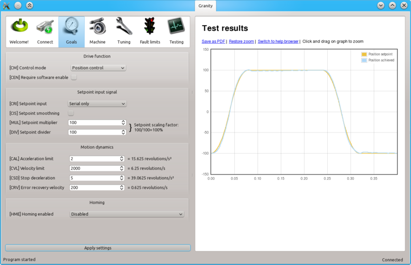
- Set drive in position control mode Control modeCM
- Choose Serial only setpoint input Control modeCM
- Make other necessary adjustments to have drive powered and enabled
- Untick Setpoint smoothingCIS
- Set Goals tab Setpoint dividerDIV and Setpoint multiplierMUL to 50
- Set Acceleration limitCAL & Velocity limitCVL limits reasonably to the levels that motor is expected to handle
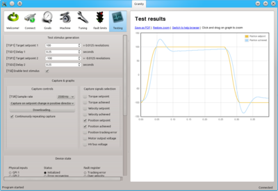
- Set-up the test stimulus and capture settings from Testing tab (an example, may be varied):
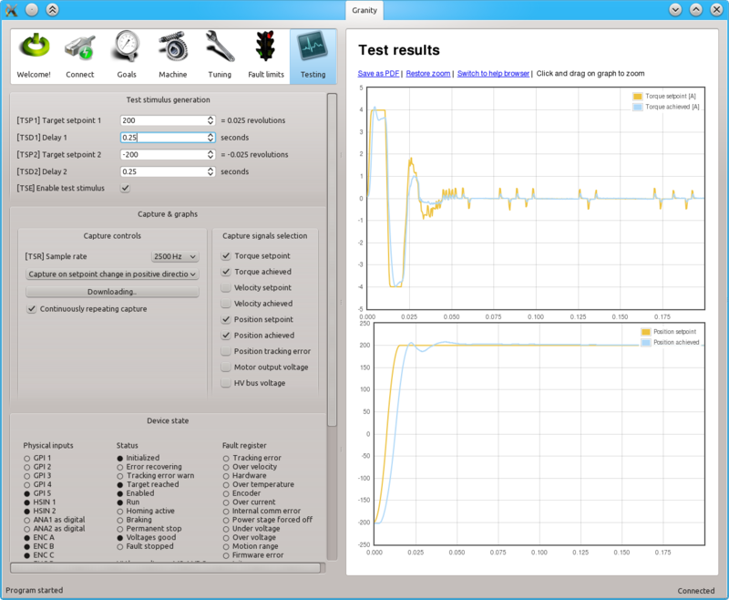
- Set target setpoint 1 TSP1 to 100
- Set delay 1 TSD1 to 0.25 seconds
- Set target setpoint 2 TSP2 to -100
- Set delay1 TSD2 to 0.25 s
- Choose Sample rateTSR of 500 to 2500 Hz
- Choose Capture setpoint change in positive direction from the dropdown
- Tick Continuously repeating capture
- Tick Position setpoint and Position achieved from signals
- Tick Start capture to begin continous capture.
- Tick Enable test stimulusTSE to begin a continuous position back and forth motion generation
Once the steps above are done, motor should be generating short distance back and forth motion motion and position response graphs should appear on the right side of Granity about once in 3-5 seconds.
Finding velocity & position control gain values[edit | edit source]
The task here is to adjust the Coil resistanceMR and Coil inductanceML parameters to achieve near optimum step response for the torque controller. Observe the images below for guidance.
| If the drive faults during this testing due to overcurrent, see Tuning torque controller for solutions. If drive faults due to following error or motion fault, increase the goal deviation fault limits at Fault limits tab. |
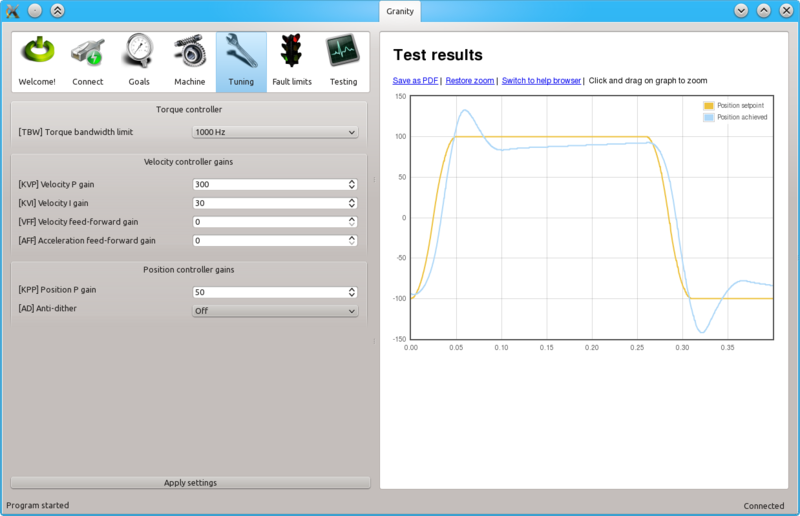
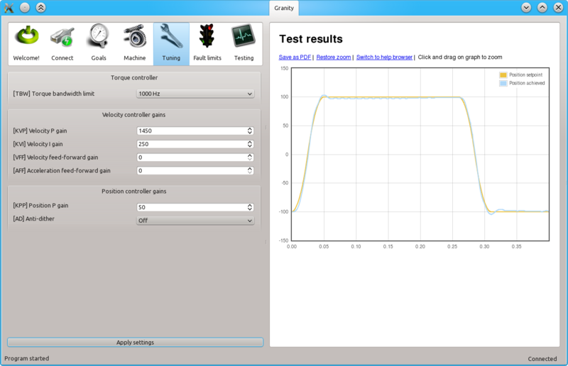
The image above represents the initial position step response with low feedback gains. As seen, motor reaction is sluggish, lagging and has overshooting.
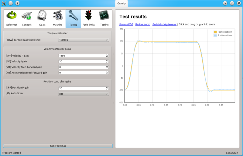
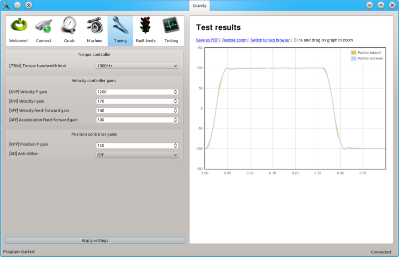
The next step is to increase Velocity P gainKVP gain as much as possible. The graph may start looking acceptable but it motor still has low stiffness thus it will get lag once mechanical load increases.
To try different gains, go to Tuning tab, change value and click the Apply settings button.
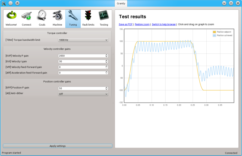
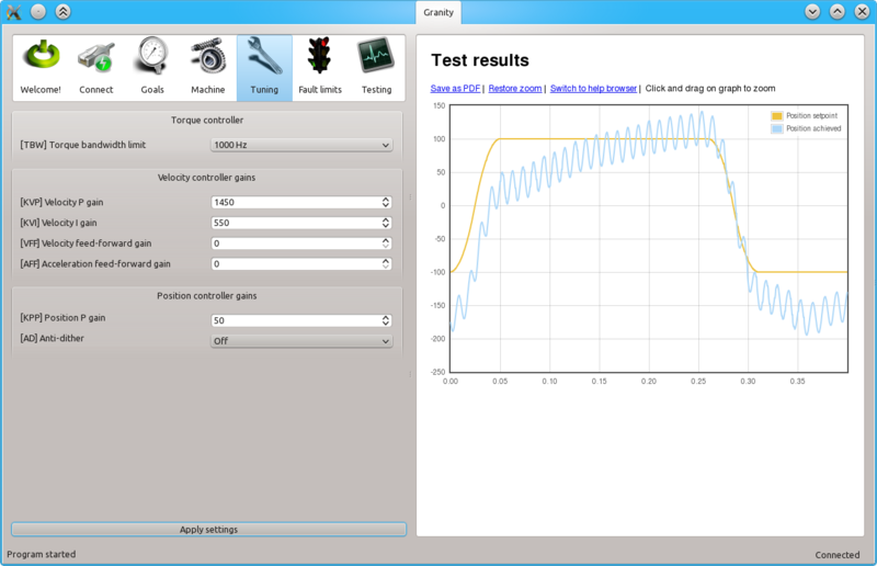
When Velocity P gainKVP has been increased too much, the system becomes unstable and may start oscillating. In such case, you may hit Esc button to disable drive, reduce the gain and enable drive again.
Tip: torque bandwidth has significant effect on the behavior of KVP value and the point where it goes unstable. One may experiment different Torque bandwidth limitTBW settings to find the optimum.
Once a maximum perfectly stable Velocity P gainKVP value has been found, start increasing Velocity I gainKVI gain by a similar fashion. The higher KVI value is, the better servo stiffness.
If Velocity P gainKVP is increased too much, the result is instability and oscillation. The cure is similar to the too high Velocity P gainKVP gain as described earlier.
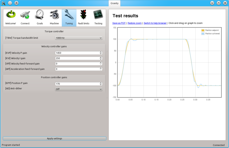
Once both Velocity P gainKVP and Velocity I gainKVI has been optimized, the next step is to increase Position P gainKPP gain the same way. Increasing Position P gainKPP gives better servo stiffness but may also increase overshooting. Overshoot less than 10 feedback device counts is generally considered good.
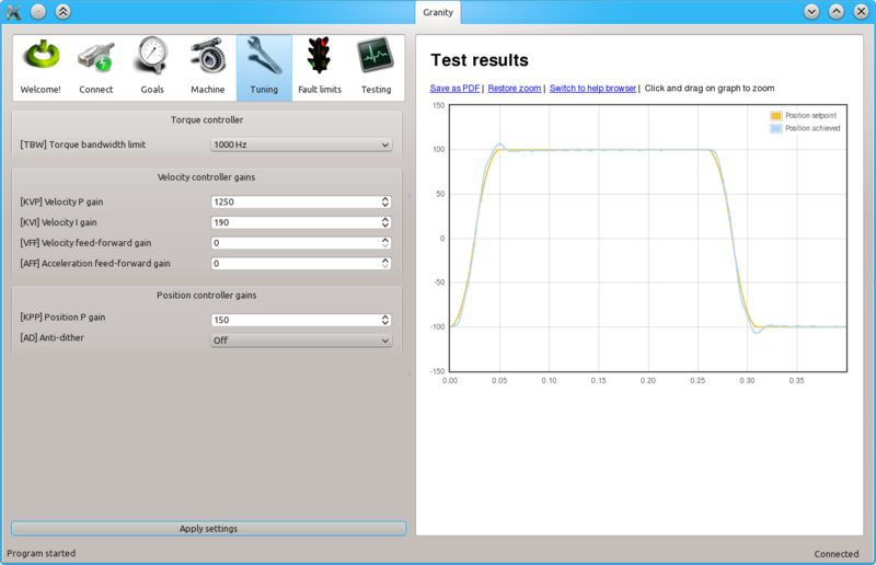
Finally after playing little bit with all of Velocity P gainKVP, Velocity I gainKVI and Position P gainKPP experimentally, we find a less overshooting response without losing much stiffness.
Curing tracking error and overshoot[edit | edit source]
If servo overshoots too much, or can't follow the trajectory precisely, several cures may be tried.
Reducing Acceleration limitCAL and/or Velocity limitCVL limits makes the trajectory easier to follow and reduces tracking error and overshooting.
The same may be also achieved by utilizing Feed-forward Velocity feed-forward gainVFF and Acceleration feed-forward gainAFF which essentially compensate system friction and mass limiting the dynamic performance.
The recommended way to tune FF gains, is to start increasing Velocity feed-forward gainVFF until the optimum level has been found. After that, increase Acceleration feed-forward gainAFF until the optimum point has been reached.
If following the tuning procedure does not result in satisfactory tracking performance, the problem may be asking too much from the motor. In the example above the acceleration limit is set too high to be accelerated with the given motor torque limits (or current limits).
To verify if the problem happens due to torque limit, tick also Torque achieved and Torque setpoint signals from the Testing tab settings. In such way also motor currents will be displayed simultaneously with the position response curves. If the torque curve is limited to the set, Peak current limitMMC, then the problem is insufficient torque. In the image above we can see that the torque curves are saturated at 4A and -4A levels which matches the configured Peak current limitMMC value of 4A in this demonstration.
To help this, try:
- Increasing Peak current limitMMC and Continuous current limitMCC if possible
- Reducing Acceleration limitCAL and/or Velocity limitCVL limits
Steps to do after tuning finished[edit | edit source]
- Stop test stimulus by unticking Enable test stimulusTSE
- Stop scope capture by unticking Continuously repeating capture
- Undo all temporary changes made to settings
- Save settings to drive memory by clicking Save settings on drive non-volatile memory button
- Set preferred setpoint source Setpoint inputCRI, also consider the use of Setpoint smoothingCIS
- If setpoint signal scaling is needed, adjust Setpoint multiplierMUL and Setpoint dividerDIV values. See Signal path of motor drive for explanation of velocity setpoint scale.
| If drive will be controlled by an external motion controller with acceleration & velocity limits, such as CNC controller programs like Mach3 or LinuxCNC, then its recommended to increase Acceleration limitCAL to the maximum value of 32767 and disable Setpoint smoothingCIS to prevent drive's internal acceleration limiter modifying the setpoint signal. Using these settings effectively disables the internal acceleration limit and let's external controller to control accelerations. |
