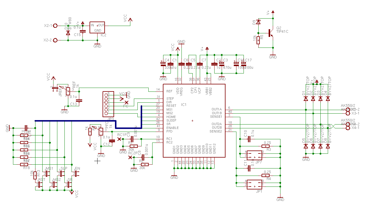
Here is the list of components. Some parts are optional, see the description below.
Part Value Package
C1 220n C050-050X075
C2 220n C050-050X075
C3 220-470u E5-10,5
C4 220-330u E2,5-7
C5 0.22u C050-030X075
C6 0.22u C050-030X075
C7 0.22u C050-030X075
C8 0.001u C025-025X050
C9 0.001u C025-025X050
C10 0.1u C050-025X075
C11 0.1u C050-025X075
C12 0.1u C050-025X075
C13 0.1u C050-025X075
C14 0.1u C050-025X075
C15 0.1u C050-025X075
C16 47u E2,5-6
C17 47u E2,5-6
**D1 BYV27 DIODE
**D2 BYV27 DIODE
**D3 BYV27 DIODE
**D4 BYV27 DIODE
**D5 BYV27 DIODE
**D6 BYV27 DIODE
**D7 BYV27 DIODE
**D8 BYV27 DIODE
*D9 Vz=34V DO34Z7
*D10 PBYR1645 TO220
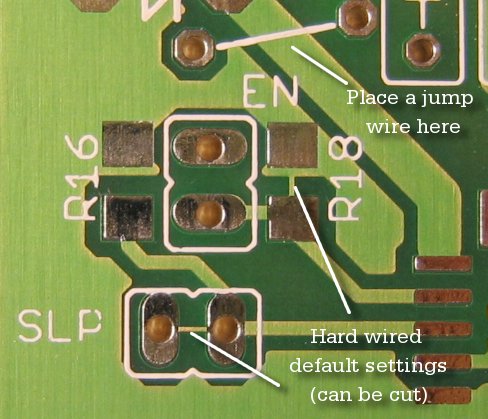
****EN JP1
IC1 A3977SED PLCC44
IC2 7805 TO220
***JP1 JP2Q
JP3 1X06
***JP7 JP2Q
****JREF JP1
MS1 JP1
MS2 JP1
PFD 1k PT-10
*Q2 TIP120-TIP122 TO220
R1 30k 0207/2V
R2 30k 0207/2V
R3 0.20 (2W) 0411V
R4 0.20 (2W) 0411V
*R5 10k 0207/2V
R8 680-820 R1206
R13 10k 0207/2V
R14 10k R1206
R15 10k R1206
R16 10k R1206
R17 10k R1206
R18 10k R1206
REF 1k PT-10
****RST JP1
****SLP JP1
****SR JP1
X2 AK500/2
X3 AK550/2 AK550/2
X4 AK550/2 AK550/2
Parts marked with stars are optional:
| * |
Overvoltage and reverse polarity protection |
| ** |
Decreases power dissipation of the chip. SR jumper must be open to get the advantage of the diodes. |
| *** |
May be used in some future expansion. |
| **** |
Hard wired jumpers. See description in next chapter. |
Capacitors below 1 µF are ceramic type.
All 10k Ohm SMD resistors are controlling logic only. You can use any resistor between 5-30 kOhm.
C16 and C17 have very limited space. Try to find largest capacitor that fits in board. Capacitor volrage rating must be at least 35V.
D10 can be almost any diode that will not break when applying reverse polarity supply voltage.
X3 and X4 are smaller type screw terminals! Lead spacing about 3.5 mm.
If you are going to solder D1-D8 don't forget to solder two jump wires near diodes!