VSD-A

Tero's Project Corner
About Project JV2
The JV2 (Jyrsin V2) is my second and better attempt to build a CNC router. As we know, hunger will get stronger while eating so after finishing JV1 I started planning a new one. This one should have more working space in smaller package :)
Plan
picture picture
I considered many different mechanical topologies and this is what I saw as one most simplest and affordable. It's mechanical propeties should't be bad either.

These cad drawins are little bit outdated now and actual machine is slightly different. One major difference is caused by different XZ-axis holder bars which origally were stron square iron pipes. After buying some iron I noticed that those were way too twisted to be mounted with linear rail. After some time I found abandoned aluminium profiles that fitted perfectly for the job :)

Another change is in dimensions. We ordered lienar rails with lenght of 500 mm, but they came 520 mm long due to hole placements. Fortunately we didn't have those aluminium chassis plates at moment so I had a chance to modify them.

Collecting parts
picture picture picture
The linear rails in the first picture are made by SBC and rail width is about 30 mm. The slide units are preloaded type to ensure good rigidity and lack of play. My plan was to use surely strong enough rails to make this single rail per axis construction possible. Those slide units have astounding properties: static load rating is more than 50 kN (~5 tons) and stationary moment 500-600 Nm depending on direction.

Pictures shows also my little 9 mm IKO miniature linear rails that I managed to buy as used. Don't let the size fool you, one of those blocks can carry about 1600 Newtons load.

The aluminiun plates are 16.5 mm thick and have pre-machined faces on both sides. However those aren't perfectly straight in all ways. Fortunately plates are curved only in one direction and the curvature is very symmetrical so it's effect is completedly cancelled by slide unit placement. The fixed slide unit just under milling head makes it extremely rigid and accurate. Rigidity decreases by some amount when moving away from center line where the rail is.

Putting things together
picture picture picture picture picture
JV2 was desinged to be buildable without existing CNC tools. However I utilized JV1 on drilling holes of linear guides. Most work is just drilling and milling parts in shape.

The Z axis unit was the most troublesome part to make. Accuracy requirements for linear slide parallelism is extremely high. First I milled the faces straight but that was not enough. I did some final lapping over mirror surface to give better finish on mounting suffaces. Even the mounting of screws affects slightly in additional friction and tension of slides.

The fourth picture shows the measuring clock on JV2 table. I tested the flatness of table surface and got ±0.01 mm maximum height deviation from whole area.

The nut solutions and couplers in these pictures are only temporary solutions and should be replaced later. Current couplers between screws and motors are just pieces of rubber tube. Tube is bit too soft and bends about angle of one fullstep when changing directions of rotation.
Anti-backlash nuts
picture
After trying various methods making accurate nuts, I finally ended up in this design. These split brass nuts can be radially tightened to very little play without increasing friction significantly. Screws are ordinary 10 mm stainless screwbar which I ground with grinding compound. Measured total backlash reading from axes is less than 0.02 mm, probably a half of that comes from cheap couplers.
Mostly finished
picture picture picture
These pictures show the JV2 in action. The last picture shows the machine in its current state.
JV2 vs JV1
picture
Here you see a comparison picture about milling areas of JV1 and JV2. One of cons in the JV1 was a small working area compared to its footprint. Things are improved a lot now, JV2 can move in 420*420*70 mm space and footprint is 520*520 mm.
Producing BCP's and nameplates
picture picture picture picture picture
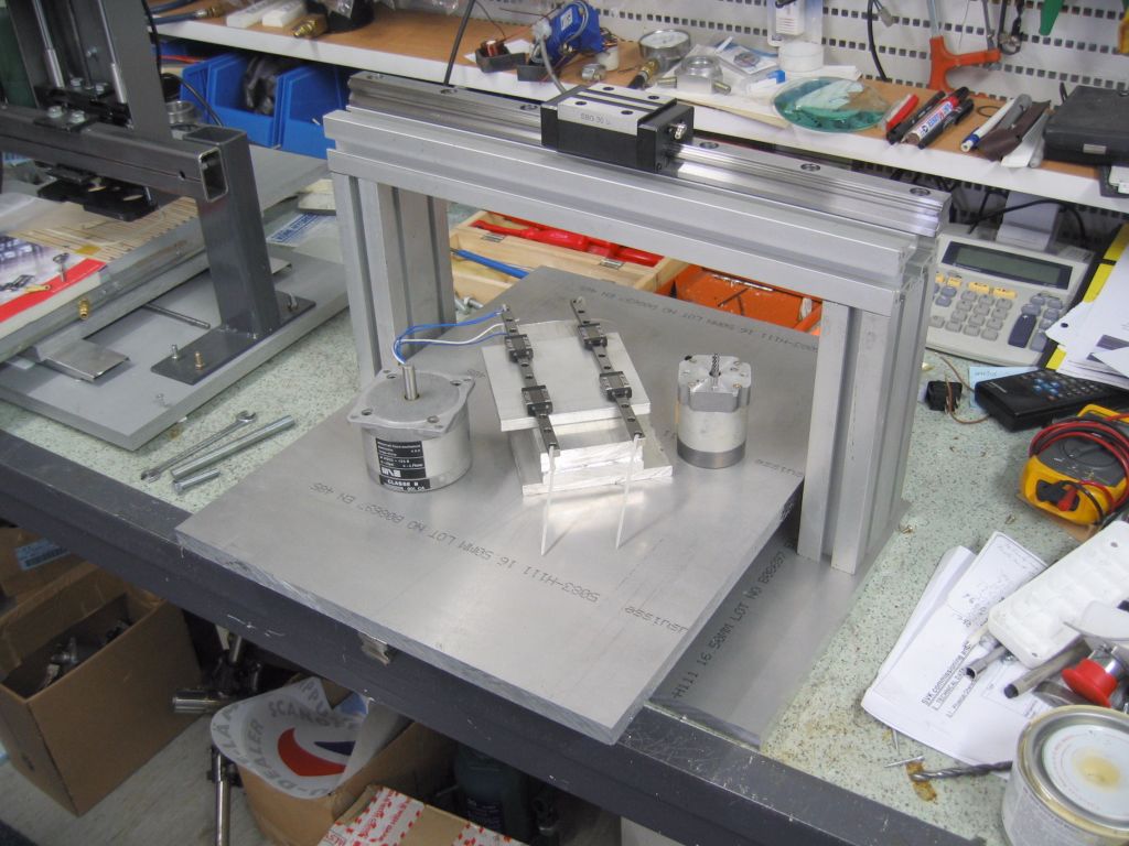
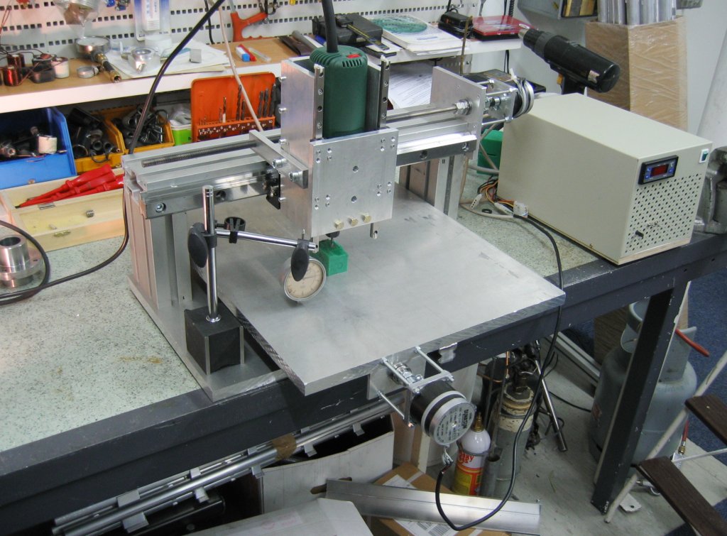
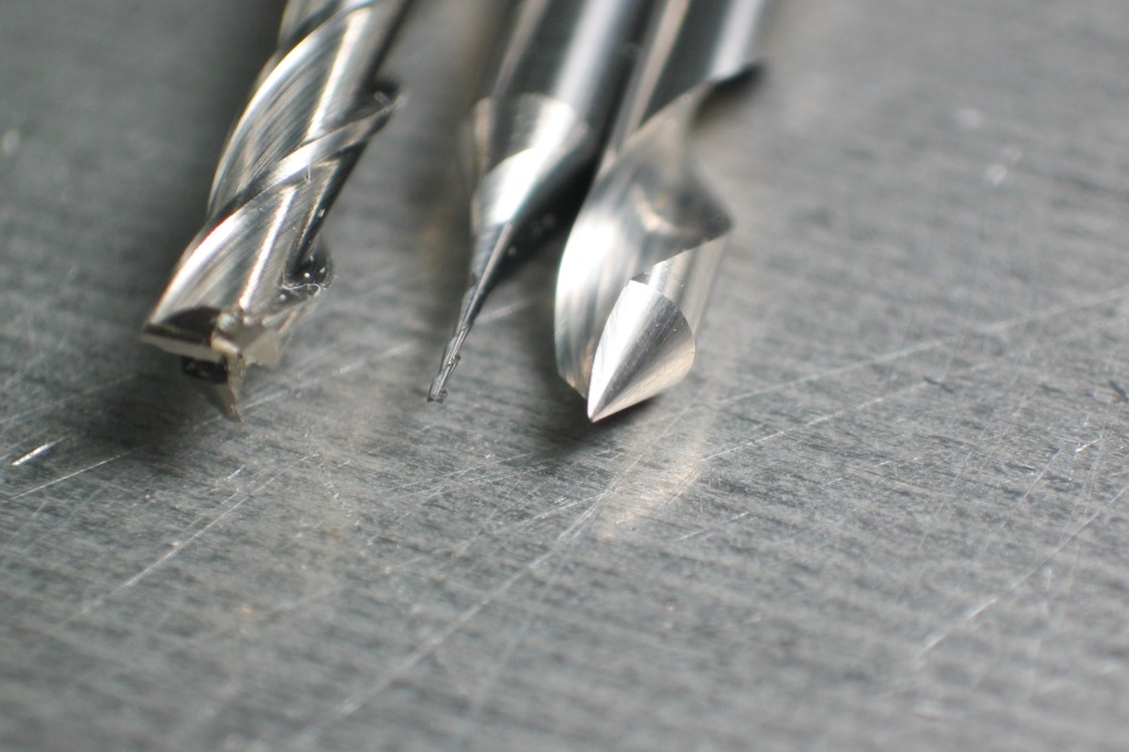
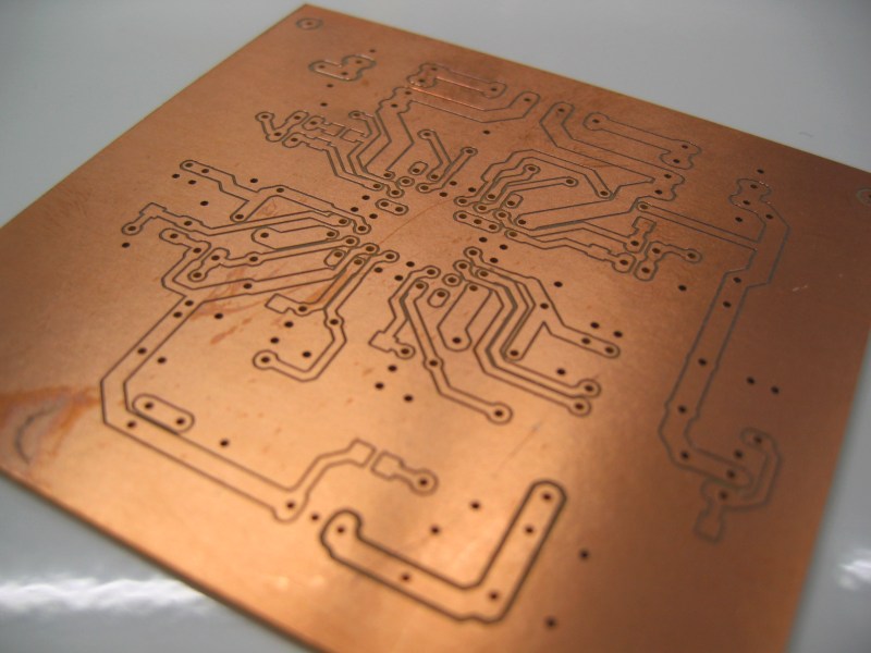
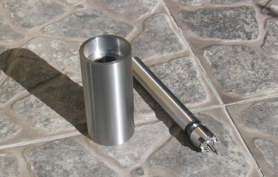
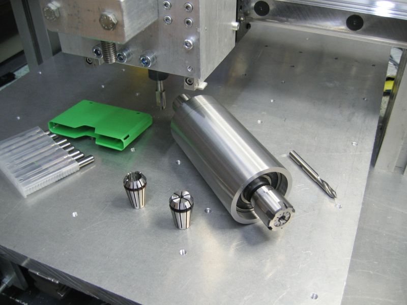
One of major JV2 usages is BCP milling. The first picture shows some tools: a normal 3 mm end mill (just for comparison), a 0.40 mm end mill and a 60⁰ cone engarver.

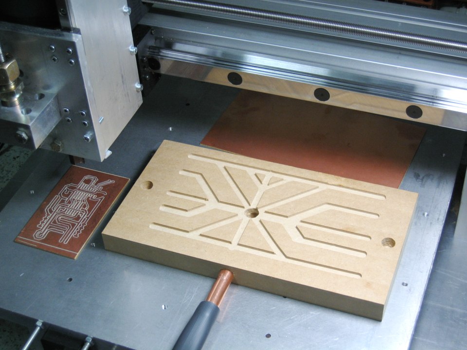
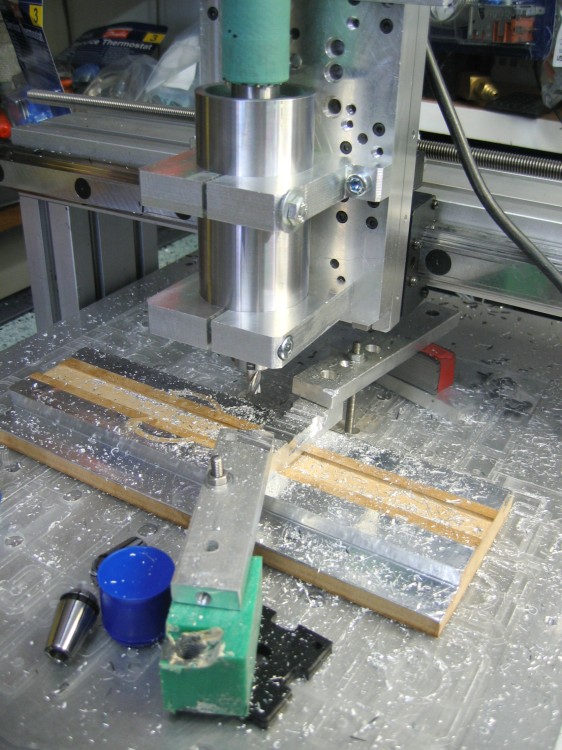
The cone engarver is extremely sensitive to height deviations so I developed a proper BCP mounting device. It is just piece of MDF which is milled flat from boths sides. It also has milled channels for suction on both sides, so it does't need any screws to attach things. Also BCP's are forced straight by vacuum cleaner.

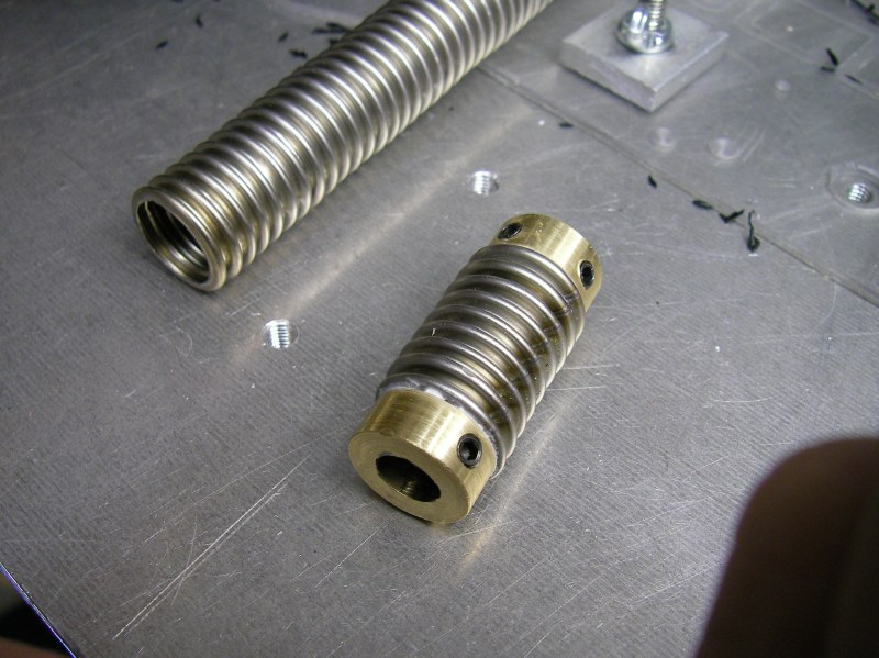
These small tools are very sensitive to radial runout. The cut is about 0.005 mm per flute per revolution so runout of 0.01 mm is far from acceptable. Bosch router can only mount tools with 8 or 6 mm shank and engarving tools have shank of 3 mm diameter, so I would need some adapter. 
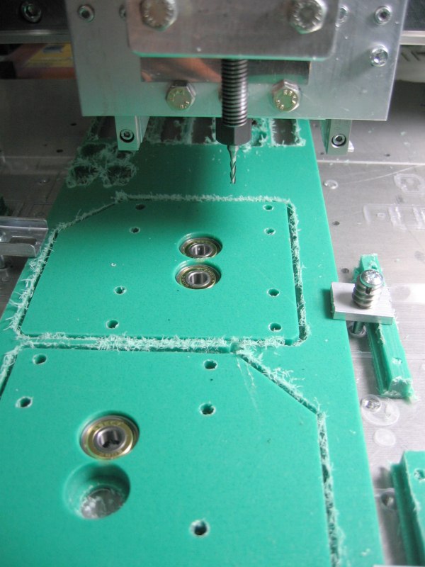
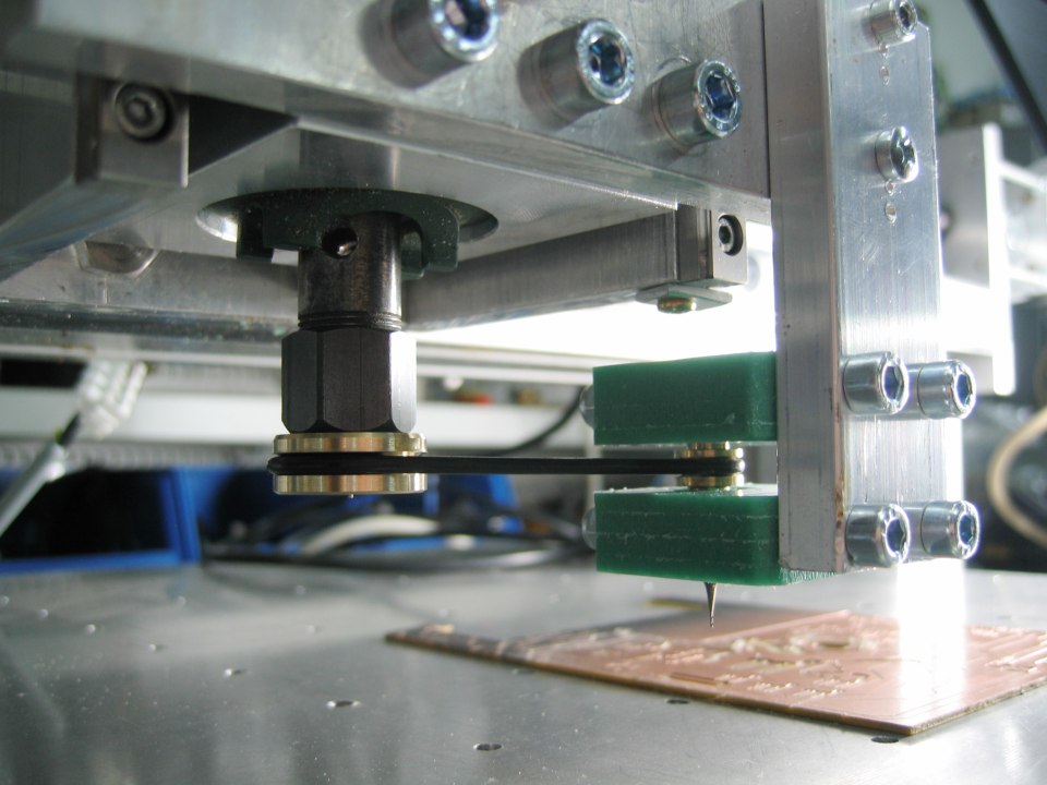
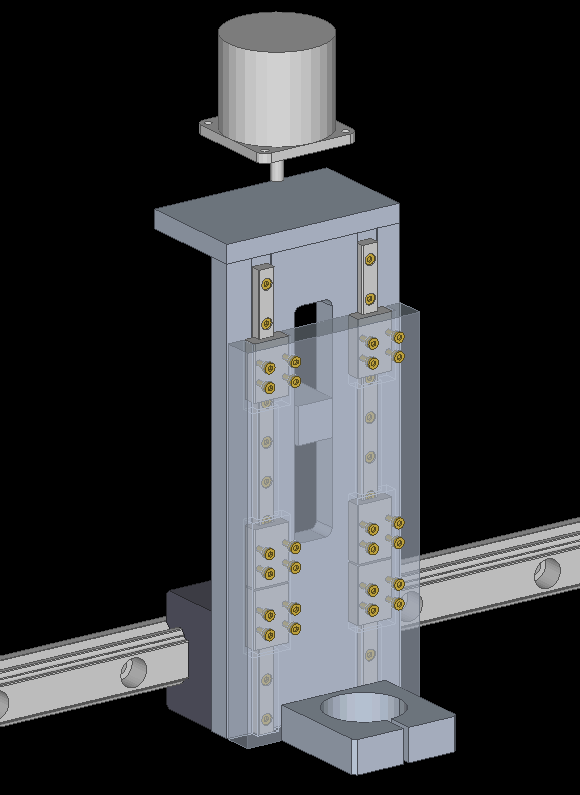
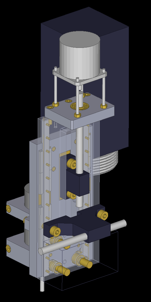
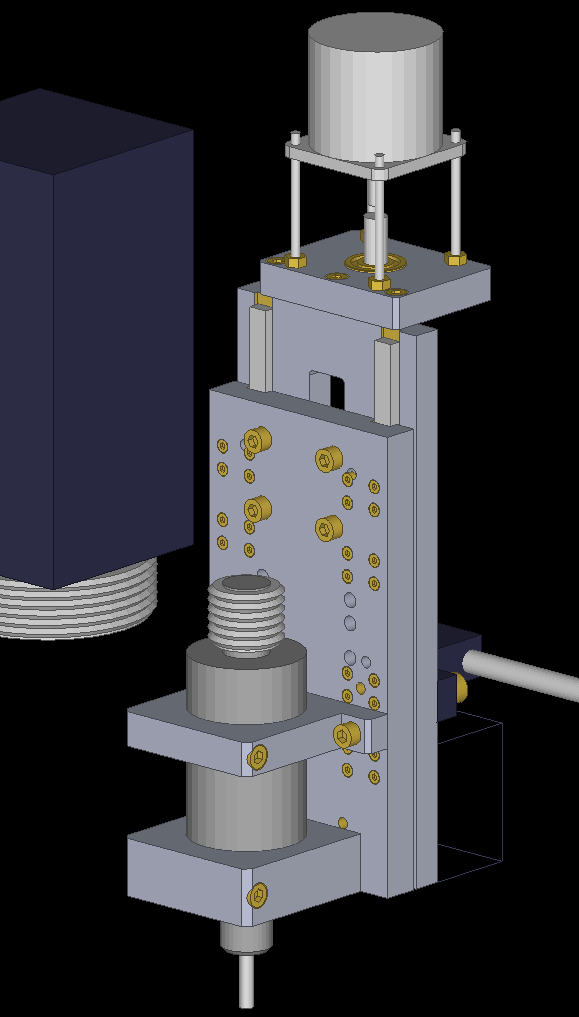
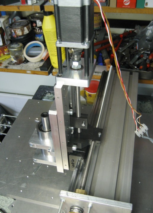
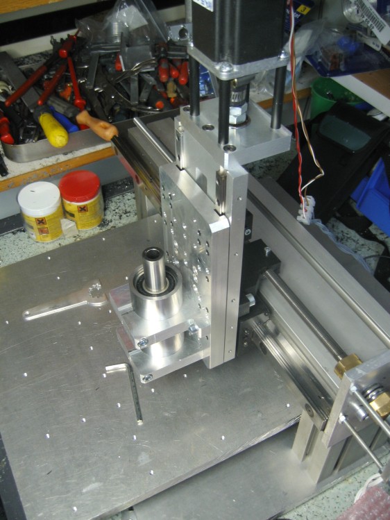
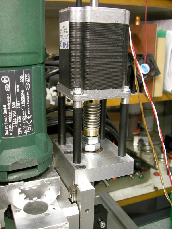
With lathe it is pracitally impossible to get accurate enough parts so I made special spindle for 3 mm tools. It is composed of two small ball bearings which are so tight that tool doesn't need any special mounting. However I used hot glue to ensure tool's position in spindle.

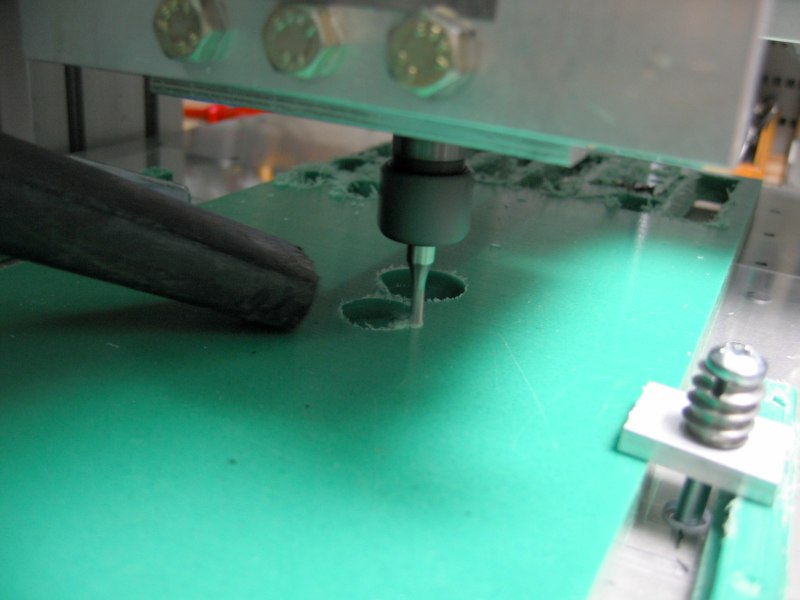
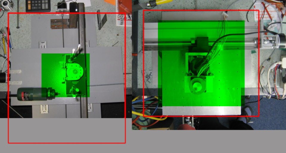
You can download JV2 BCP milling in action video clip here (3.3 MiB, MPEG4).
12.4.2005 Update: new Z axis
picture
I'm planning to replace the current Z axis of the JV2. Here is a draft what it might look like.

Here are few points that it should improve:

  • Better ergonomy. Changing tools in current Z is not very handy.
  • More room for homemade spindle with external DC motor as power source.
  • Hopefully even more rigid and precise than its predecessor.

Don't hold your breath seeing this update finished soon. There are lots of other things to do before this (BF20 for example).

24.1.2006 New Z axis progress
picture picture picture picture picture picture
I have mostly completed the desing of the Z axis replacement. Some of the largest parts have been already machined but some smaller ones are still missing like polyacetal play free nuts (the black parts in the drawings).

I switched spindle motor from DC to AC servo motor rated 2.2Nm, 4000rpm, 920W. I'm currently developing a AC servo drive electronics for this motor and for general positioning AC/DC servos too.

Here are also couple of photos of my new spindle based on Fatpol tool extender shank with ER16 collet mounting. Result is very interesting: measured radial runout is less than 0.005 mm. Our 0.01 mm dial indicator is not accurate enough to indicate such small runout.

18.4.2006 First chips with new spindle
picture picture picture
I finally had some time to machine missing parts required to assemble the new Z-unit. It still misses some smaller parts like limit switches and anti backlash nut pre-tension springs but it operates also without them.

I mounted my new spindle on it and temporarily used Bosch router to spin the thing. Bosch lacks some torque and makes awful noise so it will be replaced by AC servo as soon as possible.

The performance of the spindle is magnificent compared to the Bosch router. It makes shiny cuts in POM plastics and in aluminium. Spindle runout seems to be zero when measured using 0.01 mm dial.

29.5.2007 DIY bellows coupler
picture picture
I started experimenting with home made bellows shaft coupler. This type of couplers are preferred for precise applications because of their axial stiffness. DIY coupler was made from steel bellows tube and brass end pieces which were finally expoxed together.

This one goes for Z axis. X and Y axis couplers are not ready yet.

Copyright © 2004-2007 Tero Kontkanen. Total counter visitors.