Difference between revisions of "Servo tuning basics"
| [checked revision] | [checked revision] |
(→Gain tuning (car) example) |
(→Gain tuning (car) example) |
||
| Line 24: | Line 24: | ||
In servo drive case, this means that each motor type and mechanical axis need to be tuned separately. However, if axis and motors are identical, then the same gains should work equally. | In servo drive case, this means that each motor type and mechanical axis need to be tuned separately. However, if axis and motors are identical, then the same gains should work equally. | ||
==Gain tuning (car) example== | ==Gain tuning (car) example== | ||
| + | The following series of images illustrate an imaginary car driving scenario where the driver acts as velocity controller of the car. The magnitude of PI gain values equal the driver's aggressivity of controlling the pedal to reach the desired speed. | ||
===Low gains - sluggish response=== | ===Low gains - sluggish response=== | ||
[[File:Carexample sluggish.png|800px]] | [[File:Carexample sluggish.png|800px]] | ||
Revision as of 20:26, 12 August 2013
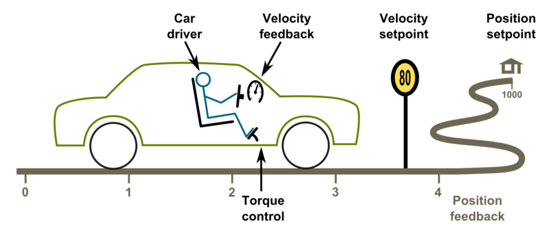
Driving a servo motor is much like driving a car. Driving a car has many similarities including the key concepts of torque, velocity and position control. Most of this happens in the driver's head the same way than a servo drive does with a motor.
Driving (a.k.a servoing) a car
Driver as a controller
What is a controller gain and a PI controller
Controller gain means sensitivity to change output due to tracking error (the difference between setpoint and feedback).
The simplest form of feedback based controller is a proportional gain controller (P controller) where output follows the formula output = Pgain*(setpoint-feedback). The problem of proportional gain controller is that it may never reach the setpoint because output starts approaching zero when the following error is reaching zero.
Because of this, it's better to add in integrating component to the controller (forming PI controller). Integrator accumulates the tracking error to a integrator variable. Integrator variable is like a bucket of water, when you add water, the water level rises and when you take out water, the level lowers. In controller the equation becomes: output = Pgain*(setpoint-feedback) + Igain*IntegralOf(setpoint-feedback).
The characteristics of feedback gain variables:
- P-gain - reacts instantly to the tracking error but can't eliminate tracking error completely
- I-gain - reacts slowly over time, adjusts output until tracking error is zero
When driving a car, human brain closely resembles the operation of a PI controller. For in-depth info about PI controllers and its variants, see the Wikipedia article PID controller.
Tuning the gains
Controller tuning means finding of the optimum gain values for the given system.
The proper gain values always depend on many aspects, especially the target system dynamic properties (such as motor properties, axis transmission ratios, inertias and masses). Change of properties introduces the requirement of tuning the gain values as gain values that work fine in one system may not behave satisfactory on a different system.
In servo drive case, this means that each motor type and mechanical axis need to be tuned separately. However, if axis and motors are identical, then the same gains should work equally.
Gain tuning (car) example
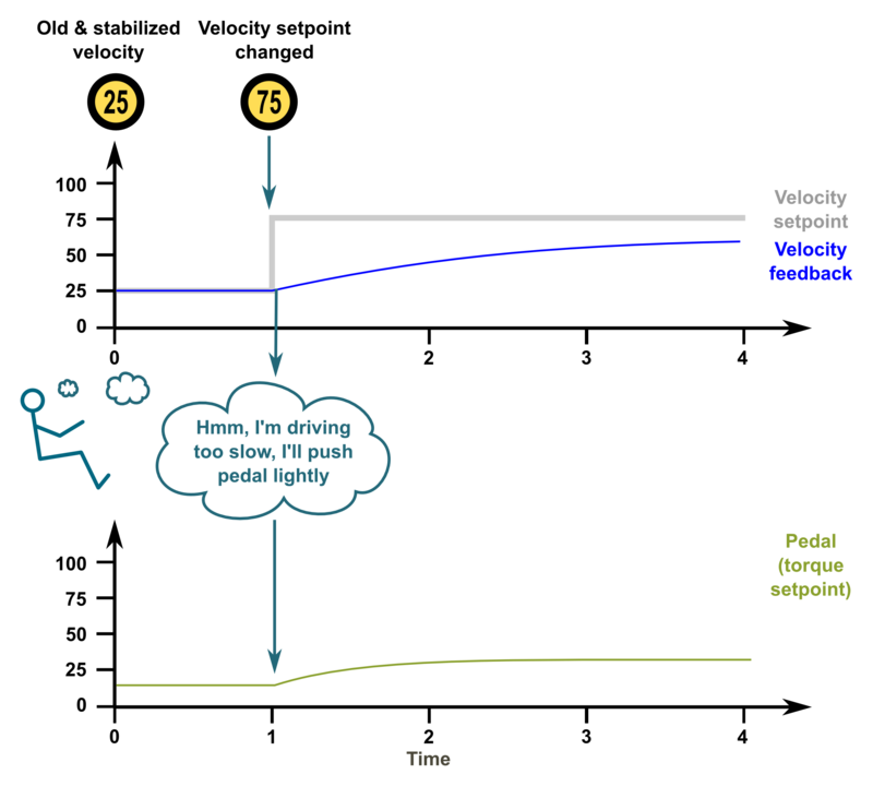
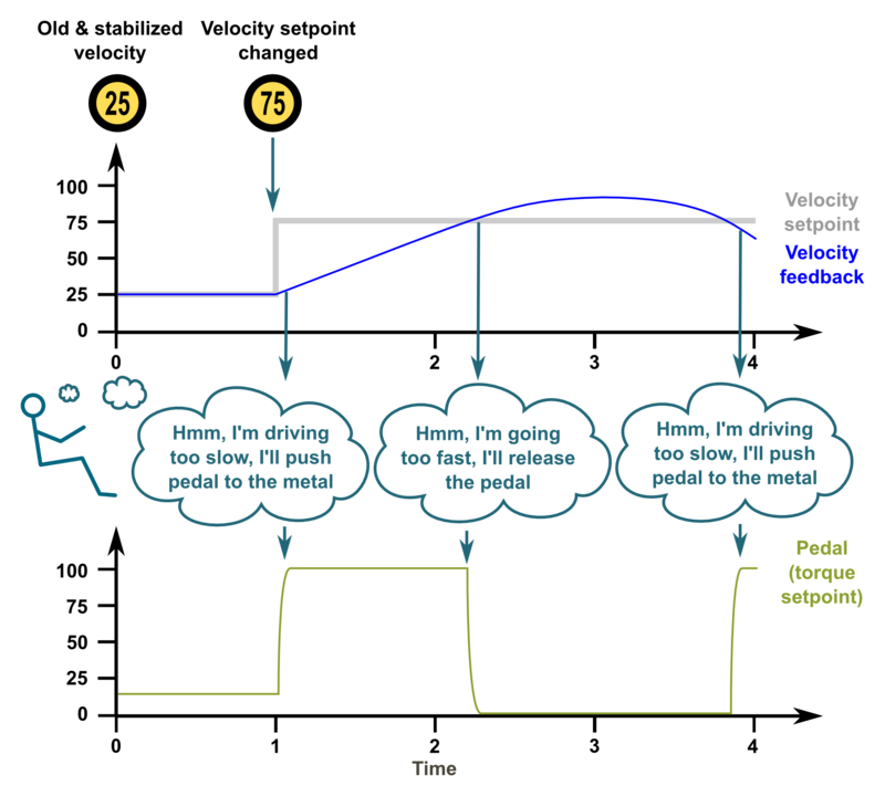
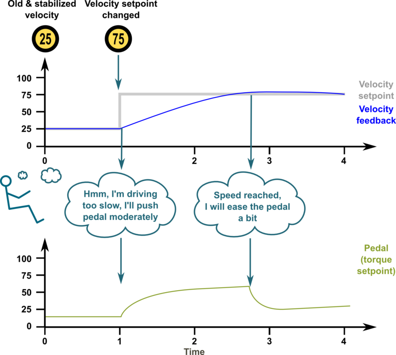
The following series of images illustrate an imaginary car driving scenario where the driver acts as velocity controller of the car. The magnitude of PI gain values equal the driver's aggressivity of controlling the pedal to reach the desired speed.
Low gains - sluggish response
If the gains are set too low, the system response tends to be sluggish and sometimes leave a static tracking error (not reaching setpoint in any time). In this imaginary case we could think PI gains to be P=20 I=10.
Too high gains - oscillation & instability
If the gains are set too high, the system becomes overshooting, oscillating and less stable. Here the comparable PI gains could be P=200 I=100
Optimum gains - only little overshoot
When the gains are tuned correctly, the response shows rapid response with low overshoot and no ringing or oscillations. The comparable gains here P=50 I=25.
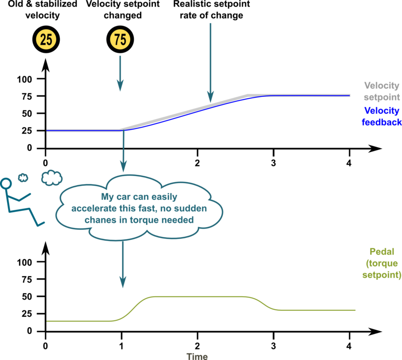
Optimum gains with realistic setpoint - optimum response
The response can be improved further by introducing a limit to the slew rate of setpoint signal. The controller behaves optimally when the system is able to follow the setpoint continuously with little tracking error. In this case the gains could be same as before, P=50 I=25.
