Difference between revisions of "Granity user guide/Testing"
| [checked revision] | [checked revision] |
(→Status) |
|||
| Line 56: | Line 56: | ||
|- | |- | ||
| Tracking error warn || True when position or velocity tracking error is greater than 1/8 of fault limit ([[FPT]] or [[FVT]]) || | | Tracking error warn || True when position or velocity tracking error is greater than 1/8 of fault limit ([[FPT]] or [[FVT]]) || | ||
| + | |- | ||
| + | | Target reached || True when drive's internal motion profiler (velocity & acceleration limited motion) has reached the user setpoint value|| | ||
| + | |- | ||
| + | | Enabled || True when drive has enabled state on. This allows drive to control motor if no faults are active.|| | ||
| + | |- | ||
| + | | Run || True when drive is initializing or controlling motor. Goes false if enabled is false or faults are active|| | ||
| + | |- | ||
| + | |Homing active|| True when drive is performing homing sequence. Goes false after homing is complete or not enabled|| | ||
| + | |- | ||
| + | | Braking|| True when motor is being braked electrically and/or mechanically|| | ||
| + | |- | ||
| + | | Permanent stop|| True when drive requires restart before continuing motor control. Goes true when changing certain parameters or if initialization fails|| Restart drive to see if the state clears. If not, check parameterization and usage errors. | ||
| + | |- | ||
| + | |Voltages good|| True when [[HV DC bus]] voltage is withing configured range (from [[FUV]] to [[FOV]])|| | ||
| + | |- | ||
| + | | Fault stopped|| True when drive is disabled true to active fault state|| Perform clear drive faults function (from Connect tab). If problem repeats, check motor & tuning parameters and operating conditions. See fault register and fault location for hints. | ||
| + | |- | ||
| + | |Ready for use|| True when drive has performed all initializations, possible homing and is enabled and running. When true, drive is ready to follow user setpoint commands|| | ||
| + | |- | ||
| + | |STO active||True when [[Safe torque off|safe torque off]] is active. In Argon this monitors only STO2.|| | ||
|} | |} | ||
| + | |||
===Fault register=== | ===Fault register=== | ||
Revision as of 13:31, 6 March 2014
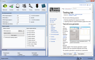
This tab serves following purposes:
- Running repeating test sequence on motor
- Capturing reference signal & feedback graphs from drive
Test stimulus generator
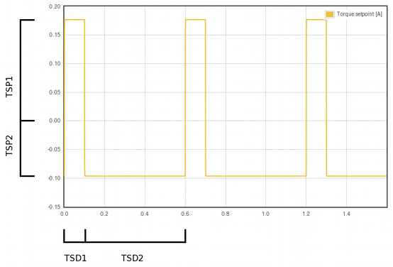
Test stimulus generator is a way to feed a repeating setpoint signal to the drive without having any other physical signals supplied. Test stimulus generates a square waveform with user specified amplitudes and timing.
The waveform generated is specified by 4 parameters:
| Short GUI name | GUI name | Description | How to use |
|---|---|---|---|
| TSP1 | Target setpoint 1 | The first setpoint level | Adjust the value and observe the right side value conversion to the real world units such as amperes or millimeters. |
| TSD1 | Delay 1 | The active duration of the first setpoint | Set the duration of the first setpoint lenght. |
| TSP2 | Target setpoint 2 | The second setpoint level | Adjust the value and observe the right side value conversion to the real world units such as amperes or millimeters. |
| TSD2 | Delay 2 | The active duration of the second setpoint | Set the duration of the second setpoint length. |
| TSE | Enable test stimulues | Control test stimulus feed | Tick this checkbox to instantly start feeding test stimulus to the drive. Before ticking ensure that setpoints are set to safe levels and always be prepared stop motor safely if unexpected motion happens. |
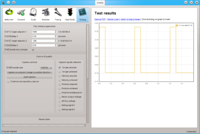
| Example where TSD1=0.1s TSD2=0.5s TSP1=1000→0.18A TSP2=-500→-0.09A |
 | ||
Set Abs and Set Inc buttons
Set Abs button set the TSP1 or TSP2 value immediately as setpoint.
Set Inc button does the same as Set Abs, but instead of setting absolute value, setpoint is being incremented. I.e. if TSP1=100 and click 5 times Set Inc, then setpoint value becomes 500.
Capture & graphs
Capture controls
Options are:
- [TSR] Sample rate - choose the sampling rate of the signals. The higher sampling rate used, the higher level detail will be captured (good to observe sharply changing edges of signal) but at the same time lenght of recorded capture will be shorter. Lower sample rate loses some detail, but gives longer capture duration.
- Capture trigger dropbox - choose one of the following:
- Capture instantly - Start capture button starts capture immediately
- Capture in fault - Start capture button waits until drive faults and begins capture at the moment of fault occurring
- Capture on setpoint change - Start capture button waits until setpoint is modified
- Capture on setpoint change in positive direction - Start capture button waits until setpoint is modified in positive direction (capture not occurring if setpoint value is reduced)
- Continuously repeating capture - if ticked, capture will be repeating continuously. Useful with test stimulus generator.
Capture signals selection
Tick the checkboxes to choose which signals to capture and display on the graph. The more signals selected, the less the capture duration will be. I.e. if one chooses 4 signals instead of 2, the time of capture will reduce to 1/2.
Device state
Devices state updates continuously while connected and shows status & fault register bits as well as state of physical I/O lines and setpoint value.
Status
| Name | Description | Troubleshooting |
|---|---|---|
| Initialized | True when drive has completed initialization procedure (such as phasing) | If never goes on, check parameters, drive input voltage, safe torque off and enable inputs and possible faults. |
| Error recovering | True when drive performs position return to the setpoint position after clear faults command is given | |
| Tracking error warn | True when position or velocity tracking error is greater than 1/8 of fault limit (FPT or FVT) | |
| Target reached | True when drive's internal motion profiler (velocity & acceleration limited motion) has reached the user setpoint value | |
| Enabled | True when drive has enabled state on. This allows drive to control motor if no faults are active. | |
| Run | True when drive is initializing or controlling motor. Goes false if enabled is false or faults are active | |
| Homing active | True when drive is performing homing sequence. Goes false after homing is complete or not enabled | |
| Braking | True when motor is being braked electrically and/or mechanically | |
| Permanent stop | True when drive requires restart before continuing motor control. Goes true when changing certain parameters or if initialization fails | Restart drive to see if the state clears. If not, check parameterization and usage errors. |
| Voltages good | True when HV DC bus voltage is withing configured range (from FUV to FOV) | |
| Fault stopped | True when drive is disabled true to active fault state | Perform clear drive faults function (from Connect tab). If problem repeats, check motor & tuning parameters and operating conditions. See fault register and fault location for hints. |
| Ready for use | True when drive has performed all initializations, possible homing and is enabled and running. When true, drive is ready to follow user setpoint commands | |
| STO active | True when safe torque off is active. In Argon this monitors only STO2. |
Fault register
Troubleshooting
- Fault location helps to identify the source of faults if nonzero

