Difference between revisions of "Argon resolver adapter"
| [checked revision] | [checked revision] |
m (Text replacement - "{{param|EMI}}" to "EMI") |
|||
| (19 intermediate revisions by the same user not shown) | |||
| Line 1: | Line 1: | ||
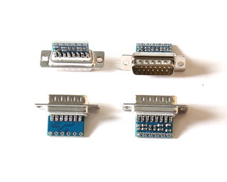
| − | [[File:Argonresolveradapter.jpg|thumb|Argon resolver adapters. These plug into Argon J1 port and resolver wires are directly connected to the pads of adapter.]] | + | [[File:Argonresolveradapter.jpg|thumb|320px|Argon resolver adapters. These plug into Argon J1 port and resolver wires are directly connected to the pads of adapter.]] |
| − | Argon resolver adapter is a small sized | + | Argon resolver adapter is a small sized device that adds [[Feedback devices|resolver]] feedback device support to [[Argon]] servo drive. |
| + | ==Obtaining adapter== | ||
| + | Adapter is available from [[Granite Devices web shop]]: | ||
| + | *[http://shop.granitedevices.com/product/38/argon-resolver-adapter Argon resolver adapter on Web shop] | ||
| + | Adapter may be also self-built (schematics: [[Media:argonresolveradapter_schematics.png]]) | ||
| + | ==Usage== | ||
| + | ===Wiring=== | ||
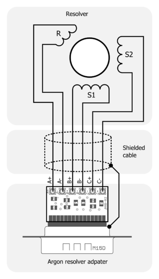
| + | [[File:Resolveradapterwiring.png|thumb|320px|Connection of resolver to adapter.]] | ||
| + | Resolver has total of 6 wires and 3 windings: one for rotor (primary) and two stators (secondaries). Rotor connects to the adapter pins A+ and A- while secondaries connect to B+/- and C+/-. | ||
| − | [[ | + | If pin-out of resolver is unknown, it can be found out with multimeter by finding the wire pairs where coils are connected. Rotor can be identified by searching for lowest resistance coil. Stators typically have at least twice as high resistance compared to rotor. |
| − | [[ | + | |
| + | A shielded cable is required and shield should be connected to D-sub connector frame to reduce [[EMI]] noise. Shielded cable for motor power leads and connection of cable shield and motor frame to drive PE is strongly recommended if not necessary to reduce noise. After all noise countermeasures, some noise is still expected from resolver read-out due to analog nature of the signals. This noise will appear as position value noise and motor hiss when standing still or rotating slowly. | ||
| + | |||
| + | Finally plug the adapter to Argon J1 port. | ||
| + | |||
| + | ===Configuration=== | ||
| + | To configure drive for resolver: | ||
| + | *Ensure that drive has at least [[Argon firmware releases|firmware]] package version 1.3.0 | ||
| + | *Choose Resolver from feedback device parameter {{param|FBD}} | ||
| + | *Set feedback device resolution {{param|FBR}} to 2048 PPR (resolver will give same resolution as 2048 PPR / 8192 count encoder). Note: 2048 is not always the correct value, see ''Multi-turn or multi-speed resolvers'' chapter. | ||
| + | *Tune motor normally. If motor is always unstable or locks motor position, try changing direction of feedback by toggling checkbox {{param|FBI}} | ||
| + | ====Multi-turn or multi-speed resolvers==== | ||
| + | Some resolvers produce more than one electrical cycle per revolution (resolver's pole pair count greater than 1). This means that also Argon sees it to produce larger position counter change per revolution. For multi pole pair resolvers, multiply the {{param|FBR}} of 2048 PPR by the number of pole pairs. For example, enter FBR value 4096 for 2 pole pair resolver and 8192 for 4 pole pair resolver. | ||
| + | |||
| + | If you're unsure of how many pole pairs the resolver has, just attach it to drive and rotate it manually exactly one revolution while inspecting position counter value at Granity's Testing tab. If you see position counter changing approx 8192 counts, then it's single-turn resolver. If you see change of ~16384 or more, then it's multi-turn resolver. To determine correct {{param|FBR}} value, write down the counter change over one revolution, divide it by 4 and round it to nearest value of 2048, 4096, 6144, 8192 or any N*2048. | ||
| + | |||
| + | Example: if you find position counter changes 16760 counts per mechanical revolution, then divide it by 4 to get 4190, then round it to 4096 which is the correct value for FBR. | ||
| + | |||
| + | [[Category:Hardware]] | ||
| + | [[Category:Argon]] | ||
Latest revision as of 20:10, 28 August 2015
Argon resolver adapter is a small sized device that adds resolver feedback device support to Argon servo drive.
Contents
Obtaining adapter[edit | edit source]
Adapter is available from Granite Devices web shop:
Adapter may be also self-built (schematics: Media:argonresolveradapter_schematics.png)
Usage[edit | edit source]
Wiring[edit | edit source]
Resolver has total of 6 wires and 3 windings: one for rotor (primary) and two stators (secondaries). Rotor connects to the adapter pins A+ and A- while secondaries connect to B+/- and C+/-.
If pin-out of resolver is unknown, it can be found out with multimeter by finding the wire pairs where coils are connected. Rotor can be identified by searching for lowest resistance coil. Stators typically have at least twice as high resistance compared to rotor.
A shielded cable is required and shield should be connected to D-sub connector frame to reduce EMI noise. Shielded cable for motor power leads and connection of cable shield and motor frame to drive PE is strongly recommended if not necessary to reduce noise. After all noise countermeasures, some noise is still expected from resolver read-out due to analog nature of the signals. This noise will appear as position value noise and motor hiss when standing still or rotating slowly.
Finally plug the adapter to Argon J1 port.
Configuration[edit | edit source]
To configure drive for resolver:
- Ensure that drive has at least firmware package version 1.3.0
- Choose Resolver from feedback device parameter Feedback deviceFBD
- Set feedback device resolution Feedback device resolutionFBR to 2048 PPR (resolver will give same resolution as 2048 PPR / 8192 count encoder). Note: 2048 is not always the correct value, see Multi-turn or multi-speed resolvers chapter.
- Tune motor normally. If motor is always unstable or locks motor position, try changing direction of feedback by toggling checkbox Invert feedback directionFBI
Multi-turn or multi-speed resolvers[edit | edit source]
Some resolvers produce more than one electrical cycle per revolution (resolver's pole pair count greater than 1). This means that also Argon sees it to produce larger position counter change per revolution. For multi pole pair resolvers, multiply the Feedback device resolutionFBR of 2048 PPR by the number of pole pairs. For example, enter FBR value 4096 for 2 pole pair resolver and 8192 for 4 pole pair resolver.
If you're unsure of how many pole pairs the resolver has, just attach it to drive and rotate it manually exactly one revolution while inspecting position counter value at Granity's Testing tab. If you see position counter changing approx 8192 counts, then it's single-turn resolver. If you see change of ~16384 or more, then it's multi-turn resolver. To determine correct Feedback device resolutionFBR value, write down the counter change over one revolution, divide it by 4 and round it to nearest value of 2048, 4096, 6144, 8192 or any N*2048.
Example: if you find position counter changes 16760 counts per mechanical revolution, then divide it by 4 to get 4190, then round it to 4096 which is the correct value for FBR.

