Difference between revisions of "Granity user guide/Testing"
| [checked revision] | [checked revision] |
(→Fault register) |
(using templates for status and fault bits) |
||
| (14 intermediate revisions by the same user not shown) | |||
| Line 3: | Line 3: | ||
* Running repeating test sequence on motor | * Running repeating test sequence on motor | ||
* Capturing reference signal & feedback graphs from drive | * Capturing reference signal & feedback graphs from drive | ||
| + | |||
| + | See also: | ||
| + | *[[Drive fault handling]] | ||
==Test stimulus generator== | ==Test stimulus generator== | ||
| Line 23: | Line 26: | ||
|TSE||Enable test stimulues|| Control test stimulus feed || Tick this checkbox to instantly start feeding test stimulus to the drive. Before ticking ensure that setpoints are set to safe levels and always be prepared stop motor safely if unexpected motion happens. | |TSE||Enable test stimulues|| Control test stimulus feed || Tick this checkbox to instantly start feeding test stimulus to the drive. Before ticking ensure that setpoints are set to safe levels and always be prepared stop motor safely if unexpected motion happens. | ||
|- | |- | ||
| − | |Example where <br>TSD1=0.1s<br> TSD2=0.5s<br> TSP1=1000→0.18A<br> TSP2=-500→-0.09A||colspan=3|<center>[[File:Stimulusgraph m.png]]</center> | + | |Example where <br>TSD1=0.1s<br> TSD2=0.5s<br> TSP1=1000→0.18A<br> TSP2=-500→-0.09A|| colspan="3" |<center>[[File:Stimulusgraph m.png]]</center> |
|} | |} | ||
| − | === | + | ===Jogging=== |
| − | '''Set Abs''' button set the TSP1 or TSP2 value immediately as setpoint. | + | '''Set Abs''' or '''Absolute set TSPx''' button set the TSP1 or TSP2 value immediately as setpoint. |
| + | |||
| + | '''Set Inc''' or '''Increment by TSPx''' button does the same as Set Abs, but instead of setting absolute value, setpoint is being incremented. I.e. if TSP1=100 and click 5 times Set Inc, then setpoint value becomes 500. | ||
| + | |||
| + | '''Set zero setpoint''' button resets setpoint to 0. Remember, if you need quick stop, rather use hotkey Esc to disable drive, or press physical E-stop button if wired. | ||
| − | |||
==Capture & graphs== | ==Capture & graphs== | ||
===Capture controls=== | ===Capture controls=== | ||
| Line 46: | Line 52: | ||
Devices state updates continuously while connected and shows status & fault register bits as well as state of physical I/O lines and setpoint value. | Devices state updates continuously while connected and shows status & fault register bits as well as state of physical I/O lines and setpoint value. | ||
| − | ===Status=== | + | ===Status bits=== |
| − | { | + | {{Template:DriveStatusbits}} |
| − | + | ||
| − | + | ||
| − | + | ||
| − | + | ||
| − | + | ||
| − | + | ||
| − | + | ||
| − | + | ||
| − | + | ||
| − | + | ||
| − | + | ||
| − | + | ||
| − | + | ||
| − | + | ||
| − | + | ||
| − | + | ||
| − | + | ||
| − | + | ||
| − | + | ||
| − | + | ||
| − | + | ||
| − | + | ||
| − | + | ||
| − | + | ||
| − | + | ||
| − | + | ||
| − | + | ||
| − | + | ||
| − | + | ||
| − | === | + | === Readings === |
{| class="wikitable" | {| class="wikitable" | ||
|- | |- | ||
| − | ! Name !! Description | + | ! Name !! Description |
| − | + | ||
| − | + | ||
| − | + | ||
| − | + | ||
| − | + | ||
| − | + | ||
| − | + | ||
| − | + | ||
| − | + | ||
| − | + | ||
| − | + | ||
| − | + | ||
|- | |- | ||
| − | | | + | | HV bus voltage || A measured [[HV DC bus]] voltage. If drive is supplied by AC voltage, then this should be approximately 1.41 times AC RMS voltage. |
|- | |- | ||
| − | | | + | |Device temperature|| Actual measured temperature if drive power stage |
|- | |- | ||
| − | | | + | |Actual current limit |
| + | |The current level which is the maximum that drive will deliver to motor at the moment. In normal case it is same as {{Param|MMC}}. If it's below it, see explanations below. | ||
|- | |- | ||
| − | | | + | |Last limit reason |
| + | |The reason why drive is or has been recently throttling current from the maximum value. Possible reasons are: | ||
| + | * None or Settings - these mean that no reason to limit current, except user parameter values such as {{Param|MMC}} | ||
| + | * [[I²t protection]] - this means that calculated motor temperature is at maximum and drive sets limit to {{Param|MCC}} | ||
| + | * Voltage - drive was unable to deliver desired current because [[HV DC bus]] voltage was insufficient to overcome motor's back-EMF voltage and other voltage losses. Increasing HV DC voltage might help to eliminate this. | ||
| + | * Temperature - device temperature causes throttling of current. Increasing cooling of device may help. | ||
| + | * Power limit - device is clipping current to avoid exceeding the maximum output power specified by {{Param|MPP}} | ||
|- | |- | ||
| − | | | + | |Output current|| Actual measured motor current |
| + | | | ||
|- | |- | ||
| − | | | + | |Velocity feedback||Actual measured velocity of motor (in physical units) |
|- | |- | ||
| − | | | + | |Velocity feedback (raw) |
| + | |Velocity feedback (in hardware scale, typically number of encoder counts moved within 400 µs period) | ||
|- | |- | ||
| − | | | + | |Position feedback ||Actual measured position of motor (hardware scale/encoder counts) |
|- | |- | ||
| − | | | + | |Setpoint value||Actual [[setpoint]] value |
| − | + | ||
|} | |} | ||
| + | ===Fault register bits=== | ||
| + | {{Template:DriveFaultbits}} | ||
==Troubleshooting== | ==Troubleshooting== | ||
*[[Fault location]] helps to identify the source of faults if nonzero | *[[Fault location]] helps to identify the source of faults if nonzero | ||
| + | {{next|[[Servo motor tuning guide]]}} | ||
| − | [[Category: | + | [[Category:Granity_user_guide]] |
Latest revision as of 14:22, 16 June 2017
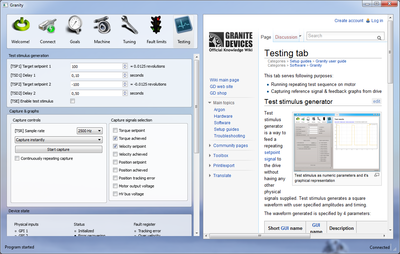
This tab serves following purposes:
- Running repeating test sequence on motor
- Capturing reference signal & feedback graphs from drive
See also:
Test stimulus generator[edit | edit source]
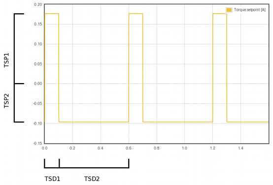
Test stimulus generator is a way to feed a repeating setpoint signal to the drive without having any other physical signals supplied. Test stimulus generates a square waveform with user specified amplitudes and timing.
The waveform generated is specified by 4 parameters:
| Short GUI name | GUI name | Description | How to use |
|---|---|---|---|
| TSP1 | Target setpoint 1 | The first setpoint level | Adjust the value and observe the right side value conversion to the real world units such as amperes or millimeters. |
| TSD1 | Delay 1 | The active duration of the first setpoint | Set the duration of the first setpoint lenght. |
| TSP2 | Target setpoint 2 | The second setpoint level | Adjust the value and observe the right side value conversion to the real world units such as amperes or millimeters. |
| TSD2 | Delay 2 | The active duration of the second setpoint | Set the duration of the second setpoint length. |
| TSE | Enable test stimulues | Control test stimulus feed | Tick this checkbox to instantly start feeding test stimulus to the drive. Before ticking ensure that setpoints are set to safe levels and always be prepared stop motor safely if unexpected motion happens. |
| Example where TSD1=0.1s TSD2=0.5s TSP1=1000→0.18A TSP2=-500→-0.09A |
 | ||
Jogging[edit | edit source]
Set Abs or Absolute set TSPx button set the TSP1 or TSP2 value immediately as setpoint.
Set Inc or Increment by TSPx button does the same as Set Abs, but instead of setting absolute value, setpoint is being incremented. I.e. if TSP1=100 and click 5 times Set Inc, then setpoint value becomes 500.
Set zero setpoint button resets setpoint to 0. Remember, if you need quick stop, rather use hotkey Esc to disable drive, or press physical E-stop button if wired.
Capture & graphs[edit | edit source]
Capture controls[edit | edit source]
Options are:
- [TSR] Sample rate - choose the sampling rate of the signals. The higher sampling rate used, the higher level detail will be captured (good to observe sharply changing edges of signal) but at the same time lenght of recorded capture will be shorter. Lower sample rate loses some detail, but gives longer capture duration.
- Capture trigger dropbox - choose one of the following:
- Capture instantly - Start capture button starts capture immediately
- Capture in fault - Start capture button waits until drive faults and begins capture at the moment of fault occurring
- Capture on setpoint change - Start capture button waits until setpoint is modified
- Capture on setpoint change in positive direction - Start capture button waits until setpoint is modified in positive direction (capture not occurring if setpoint value is reduced)
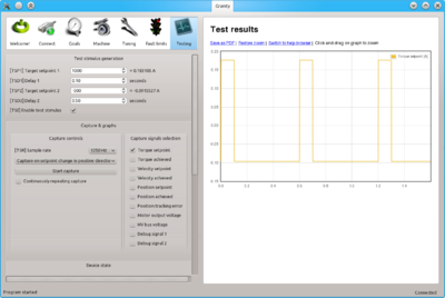
- Continuously repeating capture - if ticked, capture will be repeating continuously. Useful with test stimulus generator.
Capture signals selection[edit | edit source]
Tick the checkboxes to choose which signals to capture and display on the graph. The more signals selected, the less the capture duration will be. I.e. if one chooses 4 signals instead of 2, the time of capture will reduce to 1/2.
Device state[edit | edit source]
Devices state updates continuously while connected and shows status & fault register bits as well as state of physical I/O lines and setpoint value.
Status bits[edit | edit source]
| Name | Description | Troubleshooting |
|---|---|---|
| Initialized | True when drive has completed initialization procedure (such as phasing) | If never goes on, check parameters, drive input voltage, safe torque off and enable inputs and possible faults. |
| Error recovering | True when drive performs position return to the setpoint position after clear faults command is given | |
| Tracking error warn | Indicates that tracking error has increased beyond certain point. On most drives this controls a digital output pin that may be used in conjunction with controller to mitigate a tracking error problem before a tracking error fault is triggered. Operation depends on operating mode:
|
|
| Target reached | True when drive's internal motion profiler (velocity & acceleration limited motion) has reached the user setpoint value and other conditions are met.
Full list of conditions of this status being true are:
|
|
| Enabled | True when drive has enabled state on. This allows drive to control motor if no faults are active. | |
| Run (drive active) | True when drive is initializing or controlling motor. Goes false if enabled is false or faults are active | |
| Homing active | True when drive is performing homing sequence. Goes false after homing is complete or not enabled | |
| Braking | True when motor is being braked electrically and/or mechanically | |
| Permanent stop | True when drive requires restart before continuing motor control. Goes true when changing certain parameters or if initialization fails | Restart drive to see if the state clears. If not, check parameterization and usage errors. |
| Voltages good | True when HV DC bus voltage is withing configured range (from Under voltage fault thresholdFUV to Over voltage fault thresholdFOV) | |
| Fault stopped | True when drive is disabled true to active fault state | Perform clear drive faults function (from Connect tab). If problem repeats, check motor & tuning parameters and operating conditions. See fault register and fault location for hints. |
| Ready for use a.k.a servo ready | True when drive has performed all initializations, possible homing and is enabled and running. When true, drive is ready to follow user setpoint commands. The full logic of this bit is:
|
|
| STO active | True when safe torque off is active. In Argon this monitors only STO2. |
Readings[edit | edit source]
| Name | Description | |
|---|---|---|
| HV bus voltage | A measured HV DC bus voltage. If drive is supplied by AC voltage, then this should be approximately 1.41 times AC RMS voltage. | |
| Device temperature | Actual measured temperature if drive power stage | |
| Actual current limit | The current level which is the maximum that drive will deliver to motor at the moment. In normal case it is same as Peak current limitMMC. If it's below it, see explanations below. | |
| Last limit reason | The reason why drive is or has been recently throttling current from the maximum value. Possible reasons are:
| |
| Output current | Actual measured motor current | |
| Velocity feedback | Actual measured velocity of motor (in physical units) | |
| Velocity feedback (raw) | Velocity feedback (in hardware scale, typically number of encoder counts moved within 400 µs period) | |
| Position feedback | Actual measured position of motor (hardware scale/encoder counts) | |
| Setpoint value | Actual setpoint value |
Fault register bits[edit | edit source]
| Name | Description | Troubleshooting | Filter time before activation1 |
|---|---|---|---|
| Tracking error | Drive stopped due to position or velocity tracking error getting larger than configured limit (Position tracking error thresholdFPT or Velocity tracking error thresholdFVT) | Check settings, operating conditions and fault limits to resolve. | Goal faults filter timeFFT |
| Over velocity | Motor has exceeded the speed limit defined at Over speed faultFEV | Goal faults filter timeFFT | |
| Hardware | Drive internal error has occurred | Possibly external interference (check wiring and EMI suppression) and stability of logic supply voltage. If problem stays, contact Granite Devices support. | None |
| Over temperature | Drive temperature has exceeded its maximum value | None | |
| Feedback | Failure in feedback device has been detected | None | |
| Over current | Measured current was exceeding the limit value (current spike) | Check wiring or try different Over current toleranceFOC value | Affected by Over current toleranceFOC |
| Internal comm error | Drive internal error has occurred | Possibly external interference (check wiring and EMI suppression) and stability of logic supply voltage. If problem stays, contact Granite Devices support. | None |
| Power stage forced off | True when some of the fault states is forcing power stage off to protect drive. Motor is freely spinning unless braked mechanically. | None | |
| Under voltage | HV DC bus voltage below Under voltage fault thresholdFUV value | Check voltage, parameters and safe torque off | None |
| Over voltage | HV DC bus voltage above Over voltage fault thresholdFOV value | Check voltage and Over voltage fault thresholdFOV. If happens during motor deceleration, then a braking resistor is needed. | None |
| Motion range | Motor has been commanded outside the allowed travel boundary. I.e. driven to limit switch when Limit switch functionLFS is set to fault stop | None | |
| Firmware error | Drive internal error has occurred | Possibly external interference (check wiring and EMI suppression) and stability of logic supply voltage. If problem stays, contact Granite Devices support. | None |
| Init | Initialization failed. Possible reasons: drive disabled or faulted during initialization or initialization time-outed | Check enable signal, parameters, wiring and faults | None |
| Motion | Motor stall or loss of feedback signal detected | Adjust Motion fault thresholdFMO to larger value or disable | Goal faults filter timeFFT |
| SimpleMotion | SimpleMotion V2 Communication error detected, possibly connection lost, invalid parameter value is sent or transfer error caused by EMI or bad wiring | None | |
| Configuration | Fault caused by invalid or unstable configuration parameters | Refer to Fault location number for pin-pointing the fault source | None |
| Fault location ID | See Fault location |
1) The time duration that drive will allow fault condition be true before fault status is latched. Some faults have user adjustable time delay to reduce error sensitivity in dynamic conditions, such as rapid acceleration.
Troubleshooting[edit | edit source]
- Fault location helps to identify the source of faults if nonzero
| Read next |

