Difference between revisions of "Simucube Wireless Wheel 2"
| [unchecked revision] | [unchecked revision] |
(→Non-rechargeable version) |
|||
| (27 intermediate revisions by 4 users not shown) | |||
| Line 50: | Line 50: | ||
}} | }} | ||
}} | }} | ||
| − | The Simucube Wireless Wheel 2 Module is an upgraded version of the Simucube Wireless wheel module. | + | The Simucube Wireless Wheel 2 Module is an upgraded version of the [[SWW|Simucube Wireless wheel module]]. The new module offers more digital inputs and 4 analog axes, and includes also the battery management functions. It has a built-in charger and a voltage regulator. |
| + | |||
| + | '''Update January 31st, 2023:''' Removed mentions about the rechargeable and non-rechargeable versions of the module. Non-rechargeable version was not produced until this date, and has been discontinued (End-of-life) completely on this date. | ||
| + | |||
| + | =Digital inputs= | ||
| + | Wireless Wheel 2 Module has 98 digital input pins, of which 96 are fully configurable by wheel manufacturers. Two of the pins are reserved for shifter paddles that must be included in every steering wheel. Paddles are mandatory because they are used to connect and disconnect the wheel from Simucube. Each configurable input pin can be used multiple times with different device types. The input pins can also be used as '''''enable pins'''''. These '''''enable pins''''' can be used to enable and disable other devices. This allows for advanced functionalities, e.g., using a physical encoder as 12 virtual encoders using a rotary switch or disabling unintentional center presses in a 5 or 7-way switch.<br><br> | ||
| + | |||
| + | <u><b>Digital input device types:</b></u><br> | ||
| + | • <b>Button (regular button):</b> The game controller output signal is high if pressed.<br> | ||
| + | • <b>Encoder:</b> Each detent is shown as a pulse (25ms). The game controller has an output signal for each turning direction.<br> | ||
| + | • <b>Rotary switch:</b> Maximum of 12 positions. Changing the switch position will send a pulse (100ms) to the corresponding output. <br> | ||
| + | If the desired functionality is that the output is constantly on, the rotary switch can also be configured as regular buttons. This can also be done in addition to the default functionality if there are enough unused HID pins.<br> | ||
| + | • <b>Simucube Button:</b> Holding down this button more than 1 second will start or stop Simucube Button mode. When at this mode, user can change Simucube force feedback paramerers using buttons and encoders from wheel.<br><br> | ||
| + | |||
| + | ===Simucube Button=== | ||
| + | Holding down the Simucube Button over one second will switch Simucube 2 to Simucube Button mode, where force feedback parameters can be changed using the Wireless Wheel. | ||
| + | Sc Button mode is designed around a 7-way switch (“Funky Switch”) with an encoder and a five-way joystick. Other buttons can also be used, but it is recommended to keep layout similar between different wheels. | ||
| + | When entering SC button mode, the overall strength parameter is selected by default. The adjusted parameter is selected by configurable buttons. Holding parameter selection down for more than 2 seconds will reset the parameter to the previous value (Last value set from True Drive).<br><br> | ||
| + | |||
| + | <u><b>The function of inputs when in Sc Button mode:</b></u><br> | ||
| + | • <b>Encoder:</b> Changes currently selected parameter<br> | ||
| + | • <b>Up:</b> Overall strength<br> | ||
| + | • <b>Left:</b> Damping<br> | ||
| + | • <b>Right:</b> Simucube Force Reconstruction filter<br> | ||
| + | • <b>Down:</b> TBD<br> | ||
=Analog inputs= | =Analog inputs= | ||
| − | [[ | + | [[file:SLEEP_pin_controlled_output.png|thumbnail|upright|left|SLEEP pin with transistors can be used to turn external devices on and off]] |
| − | + | The wireless module offers an AVCC output pin for analog devices. To reduce power consumption, the AVCC pin is pulsed so that the pin is only turned on when the ADC module is sampling inputs. Output pulses are approximately 2ms long, and the frequency is 100Hz; this means that AVCC is on 20% of the time. Pulses work great with potentiometers, but Hall-effect sensors might not work with pulsed AVCC if Hall-sensor power-on time is too long. As a result, any excess capacitance must be avoided in the AVCC pin. <br> <br> | |
| + | The backup option is to provide VCC for Hall-sensors is to power it from the 3v VDD pin and use MOSFETs connected to the SLEEP pin so Hall-sensor can be powered off while Wireless Wheel 2 isn’t connected. SLEEP pin is high when Wireless Wheel 2 is connected to Simucube. See the example in the picture. In example picture VDD is 3v output from Wireless Wheel module 2 and V+ is VDD for Hall-sensors. | ||
| + | <br style="clear:both;" /> | ||
| − | = | + | = Battery connections = |
| + | Wireless Wheel 2 Module has multiple VIN, GND, BATT, and SW_IN pins for redundancy. It is recommended to tie them together to ensure a reliable connection with the M.2 connector in mechanical shock or shaking.<br><br> | ||
| + | <b>BATT and SW_IN must be connected with external switch or shorted. Otherwise the BLE2 module DO NOT GET ANY POWER!</b> | ||
| + | == Rechargeable version == | ||
| + | [[file:rechargeable_wheel_example.png|thumbnail|upright|left|Rechargeable example]] | ||
| + | The rechargeable version has a built-in charger circuit and a DC-DC converter to regulate battery voltage to 3.0V. The charger is connected to VIN and should be provided with 5.0V +- 5% with a minimum of 450mA for charging (e.g. using a USB cable). BATT pins are charger output, and the battery should be connected between these and GND. SW_IN is unregulated voltage input for the Module and will provide voltage to the in-built DC-DC converter. The power switch must be connected between SW_IN pins and the positive battery terminal. Installing a power switch between SW_IN and BATT enables charging when the wheel is turned off.<br><br> | ||
| + | <b>The integrated battery charger is suitable to be used only with Li-Po or Li-Ion rechargeable batteries that are suitable for being recharged with 490 mA current.<br> | ||
| + | No other battery types are supported!<br> | ||
| + | Using any other battery type can result in damages for example to, but not limited to, the battery, Wireless Wheel 2 module, and/or wheel in which the Wireless Wheel 2 module is installed to!<br><br> | ||
| + | Granite Devices is not responsible for any damages caused by using the Wireless Wheel 2 module in any way not specified in this document!</b><br><br> | ||
| + | <br style="clear:both;" /> | ||
| + | == Non-rechargeable version (EOL, not available) == | ||
| + | [[file:non-rechargeable_wheel_example.png|thumbnail|upright|left|Non-rechargeable example]] | ||
| + | The non-rechargeable version does not have a charger or DC-DC converter and is intended for non-rechargeable batteries. Due to a non-existing DC-DC converter, all module voltages will be the same as battery voltage. Even though it is possible to connect batteries straight to SW_IN pins to power this version, it is recommended to connect battery positive lead to VIN, which is internally connected to BATT pins in a non-rechargeable version and includes reverse polarity protection. If a power switch is needed, it can be installed on battery leads or between BATT and SW_IN pins. BATT pins should be connected to SW_IN pins to establish power for the module if the power switch is not connected between mentioned pins. | ||
| + | <br style="clear:both;" /> | ||
| + | |||
| + | = Pinout = | ||
| + | [[File:SWW2_Pin_numbering.png|thumbnail|upright|left|300px|Connector naming and pin numbering]] | ||
Wireless Wheel 2 Module uses M.2 connectors to fit all the I/O pins in a compact, low-profile packet. | Wireless Wheel 2 Module uses M.2 connectors to fit all the I/O pins in a compact, low-profile packet. | ||
All LED pins include a 220 Ohm current limiter resistor. | All LED pins include a 220 Ohm current limiter resistor. | ||
| − | + | <br style="clear:both;" /> | |
==Left M.2 connector== | ==Left M.2 connector== | ||
{| class="wikitable" | {| class="wikitable" | ||
| Line 194: | Line 237: | ||
| LED indicator for battery charging<br>Connect LED Anode to BATT || LED_CHG || 18 || 19 || BTN39 || Input | | LED indicator for battery charging<br>Connect LED Anode to BATT || LED_CHG || 18 || 19 || BTN39 || Input | ||
|- | |- | ||
| − | | rowspan="2"| SWITCH_IN operating voltage input || | + | | rowspan="2"| SWITCH_IN operating voltage input || SW_IN || 16 || 17 || BTN40 || Input |
|- | |- | ||
| − | | | + | | SW_IN|| 14 || 15 || BTN41 || Input |
|- | |- | ||
| − | | rowspan="2"| LiPO/Ion/battery positive terminal || BATT | + | | rowspan="2"| LiPO/Ion/battery positive terminal || BATT || 12 || 13 || BTN42 || Input |
|- | |- | ||
| − | | BATT | + | | BATT || 10 || 11 || BTN43 || Input |
|- | |- | ||
| rowspan="2"| GND || GND || 8 || 9 || BTN44 || Input | | rowspan="2"| GND || GND || 8 || 9 || BTN44 || Input | ||
| Line 213: | Line 256: | ||
|} | |} | ||
| − | + | =Resources= | |
| − | + | Footprint and 3D-model is using the following components:<br> | |
| + | {| class="wikitable" | ||
| + | |- | ||
| + | | Name || Manufacturer || MPN | ||
| + | |- | ||
| + | | M.2 connector || TE Connectivity || 1-2199119-5 | ||
| + | |- | ||
| + | | Spacer || Wurth || 9774015151R | ||
| + | |- | ||
| + | | M2.5x3 screws || || | ||
| + | |} | ||
| + | |||
| + | <b>Technical drawing and tolerances for Wireless Wheel 2 Module footprint</b><br> | ||
| + | [[Media:Wireless_Wheel_2_footprint_tolerances.pdf|Wireless Wheel 2 Module footprint and tolerances (.pdf)]] | ||
| + | |||
| + | ==Eagle library== | ||
| + | <b>The Eagle footprint is designed to be used with TE 1-2199119-x M.2 connector. If any other M.2 connector is used, the footprint must be corrected, as the location pins under the M.2 connector are not identical between different manufacturers and models!</b><br> | ||
[[Media:wireless_wheel_2_eagle_library.zip|Eagle library of Wireless Wheel 2 Module]] | [[Media:wireless_wheel_2_eagle_library.zip|Eagle library of Wireless Wheel 2 Module]] | ||
| − | + | ==3D-model== | |
[[Media:Wireless_Wheel_2_Module_3d.zip|Wireless Wheel 2 Module 3D model file (.step)]] | [[Media:Wireless_Wheel_2_Module_3d.zip|Wireless Wheel 2 Module 3D model file (.step)]] | ||
| + | |||
| + | =Availability= | ||
| + | Simucube Wireless Wheel 2 modules are sold to commercial sim racing steering wheel manufacturers. Contact [mailto:sales@granitedevices.com sales@granitedevices.com] for any enquiries. | ||
[[Category:Hardware]] | [[Category:Hardware]] | ||
[[Category:Simucube_2]] | [[Category:Simucube_2]] | ||
Latest revision as of 18:53, 31 January 2023
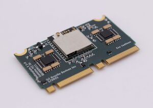
The Simucube Wireless Wheel 2 Module is an upgraded version of the Simucube Wireless wheel module. The new module offers more digital inputs and 4 analog axes, and includes also the battery management functions. It has a built-in charger and a voltage regulator.
Update January 31st, 2023: Removed mentions about the rechargeable and non-rechargeable versions of the module. Non-rechargeable version was not produced until this date, and has been discontinued (End-of-life) completely on this date.
Contents
Digital inputs[edit | edit source]
Wireless Wheel 2 Module has 98 digital input pins, of which 96 are fully configurable by wheel manufacturers. Two of the pins are reserved for shifter paddles that must be included in every steering wheel. Paddles are mandatory because they are used to connect and disconnect the wheel from Simucube. Each configurable input pin can be used multiple times with different device types. The input pins can also be used as enable pins. These enable pins can be used to enable and disable other devices. This allows for advanced functionalities, e.g., using a physical encoder as 12 virtual encoders using a rotary switch or disabling unintentional center presses in a 5 or 7-way switch.
Digital input device types:
• Button (regular button): The game controller output signal is high if pressed.
• Encoder: Each detent is shown as a pulse (25ms). The game controller has an output signal for each turning direction.
• Rotary switch: Maximum of 12 positions. Changing the switch position will send a pulse (100ms) to the corresponding output.
If the desired functionality is that the output is constantly on, the rotary switch can also be configured as regular buttons. This can also be done in addition to the default functionality if there are enough unused HID pins.
• Simucube Button: Holding down this button more than 1 second will start or stop Simucube Button mode. When at this mode, user can change Simucube force feedback paramerers using buttons and encoders from wheel.
Simucube Button[edit | edit source]
Holding down the Simucube Button over one second will switch Simucube 2 to Simucube Button mode, where force feedback parameters can be changed using the Wireless Wheel.
Sc Button mode is designed around a 7-way switch (“Funky Switch”) with an encoder and a five-way joystick. Other buttons can also be used, but it is recommended to keep layout similar between different wheels.
When entering SC button mode, the overall strength parameter is selected by default. The adjusted parameter is selected by configurable buttons. Holding parameter selection down for more than 2 seconds will reset the parameter to the previous value (Last value set from True Drive).
The function of inputs when in Sc Button mode:
• Encoder: Changes currently selected parameter
• Up: Overall strength
• Left: Damping
• Right: Simucube Force Reconstruction filter
• Down: TBD
Analog inputs[edit | edit source]
The wireless module offers an AVCC output pin for analog devices. To reduce power consumption, the AVCC pin is pulsed so that the pin is only turned on when the ADC module is sampling inputs. Output pulses are approximately 2ms long, and the frequency is 100Hz; this means that AVCC is on 20% of the time. Pulses work great with potentiometers, but Hall-effect sensors might not work with pulsed AVCC if Hall-sensor power-on time is too long. As a result, any excess capacitance must be avoided in the AVCC pin.
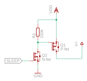
The backup option is to provide VCC for Hall-sensors is to power it from the 3v VDD pin and use MOSFETs connected to the SLEEP pin so Hall-sensor can be powered off while Wireless Wheel 2 isn’t connected. SLEEP pin is high when Wireless Wheel 2 is connected to Simucube. See the example in the picture. In example picture VDD is 3v output from Wireless Wheel module 2 and V+ is VDD for Hall-sensors.
Battery connections[edit | edit source]
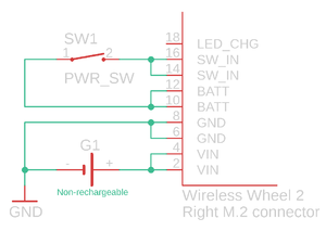
Wireless Wheel 2 Module has multiple VIN, GND, BATT, and SW_IN pins for redundancy. It is recommended to tie them together to ensure a reliable connection with the M.2 connector in mechanical shock or shaking.
BATT and SW_IN must be connected with external switch or shorted. Otherwise the BLE2 module DO NOT GET ANY POWER!
Rechargeable version[edit | edit source]
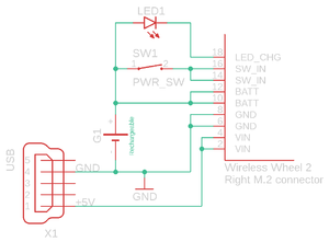
The rechargeable version has a built-in charger circuit and a DC-DC converter to regulate battery voltage to 3.0V. The charger is connected to VIN and should be provided with 5.0V +- 5% with a minimum of 450mA for charging (e.g. using a USB cable). BATT pins are charger output, and the battery should be connected between these and GND. SW_IN is unregulated voltage input for the Module and will provide voltage to the in-built DC-DC converter. The power switch must be connected between SW_IN pins and the positive battery terminal. Installing a power switch between SW_IN and BATT enables charging when the wheel is turned off.
The integrated battery charger is suitable to be used only with Li-Po or Li-Ion rechargeable batteries that are suitable for being recharged with 490 mA current.
No other battery types are supported!
Using any other battery type can result in damages for example to, but not limited to, the battery, Wireless Wheel 2 module, and/or wheel in which the Wireless Wheel 2 module is installed to!
Granite Devices is not responsible for any damages caused by using the Wireless Wheel 2 module in any way not specified in this document!
Non-rechargeable version (EOL, not available)[edit | edit source]
The non-rechargeable version does not have a charger or DC-DC converter and is intended for non-rechargeable batteries. Due to a non-existing DC-DC converter, all module voltages will be the same as battery voltage. Even though it is possible to connect batteries straight to SW_IN pins to power this version, it is recommended to connect battery positive lead to VIN, which is internally connected to BATT pins in a non-rechargeable version and includes reverse polarity protection. If a power switch is needed, it can be installed on battery leads or between BATT and SW_IN pins. BATT pins should be connected to SW_IN pins to establish power for the module if the power switch is not connected between mentioned pins.
Pinout[edit | edit source]
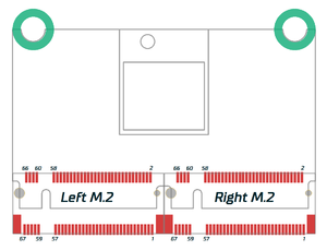
Wireless Wheel 2 Module uses M.2 connectors to fit all the I/O pins in a compact, low-profile packet.
All LED pins include a 220 Ohm current limiter resistor.
Left M.2 connector[edit | edit source]
| Bottom side | Top side | ||||
|---|---|---|---|---|---|
| Function | Signal | Pin | Signal | Function | |
| GND | GND | 66 | 67 | AVCC | 3.0 V OUTPUT to analog circuitry Max. 100 mA including VDD current. |
| GND | GND | 64 | 65 | AN0 | ADC CH0 INPUT 0 .. 3.0 V voltage range |
| GND | GND | 62 | 63 | AN1 | ADC CH1 INPUT 0 .. 3.0 V voltage range |
| GND | GND | 60 | 61 | AN2 | ADC CH2 INPUT 0 .. 3.0 V voltage range |
| Input | BTN64 | 58 | 59 | AN3 | ADC CH3 INPUT 0 .. 3.0 V voltage range |
| Input | BTN63 | 56 | 57 | BTN1 | Input |
| Input | BTN62 | 54 | 55 | BTN2 | Input |
| Input | BTN61 | 52 | 53 | BTN3 | Input |
| Input | BTN60 | 50 | 51 | BTN4 | Input |
| Input | BTN89 | 48 | 49 | BTN5 | Input |
| Input | BTN58 | 46 | 47 | BTN6 | Input |
| Input | BTN57 | 44 | 45 | BTN7 | Input |
| Input | BTN56 | 42 | 43 | BTN8 | Input |
| Input | BTN55 | 40 | 41 | BTN9 | Input |
| Input | BTN54 | 38 | 39 | BTN10 | Input |
| Input | BTN53 | 36 | 37 | BTN11 | Input |
| Input | BTN52 | 34 | 35 | BTN12 | Input |
| Input | BTN51 | 32 | 33 | BTN13 | Input |
| Input | BTN50 | 30 | 31 | BTN14 | Input |
| Input | BTN49 | 28 | 29 | BTN15 | Input |
| GND | GND | 26 | 27 | BTN16 | Input |
| Input | BTN80 | 24 | 25 | GND | GND |
| Input | BTN78 | 22 | 23 | BTN79 | Input |
| Input | BTN76 | 20 | 21 | BTN77 | Input |
| Input | BTN74 | 18 | 19 | BTN75 | Input |
| Input | BTN72 | 16 | 17 | BTN73 | Input |
| Input | BTN70 | 14 | 15 | BTN71 | Input |
| Input | BTN68 | 12 | 13 | BTN69 | Input |
| Input | BTN66 | 10 | 11 | BTN67 | Input |
| Input | BTN17 | 8 | 9 | BTN65 | Input |
| Input | BTN19 | 6 | 7 | BTN18 | Input |
| Input | BTN32 | 4 | 5 | LED1 | 3.0 V status LED OUTPUT through 220 Ohm series resistor |
| Input | BTN30 | 2 | 3 | BTN20 | Input |
| - | - | - | 1 | BTN31 | Input |
Right M.2 connector[edit | edit source]
| Bottom side | Top side | ||||
|---|---|---|---|---|---|
| Function | Signal | Pin | Signal | Function | |
| Input | BTN28 | 66 | 67 | BTN29 | Input |
| Input | BTN26 | 64 | 65 | BTN27 | Input |
| Input | BTN22 | 62 | 63 | BTN25 | Input |
| Input | BTN24 | 60 | 61 | BTN21 | Input |
| Do not connect | - | 58 | 59 | BTN23 | Input |
| Do not connect | - | 56 | 57 | - | Do not connect |
| Input | BTN96 | 54 | 55 | - | Do not connect |
| Input | BTN95 | 52 | 53 | - | Do not connect |
| Input | BTN94 | 50 | 51 | - | Do not connect |
| Input | BTN93 | 48 | 49 | - | Do not connect |
| Input | BTN92 | 46 | 47 | SLEEP | BP2 module sleep status Active LOW (BP2 sleeps) |
| Input | BTN91 | 44 | 45 | TX | LEUART TX signal OUTPUT |
| Input | BTN90 | 42 | 43 | RX | LEUART RX signal INPUT |
| Input | BTN89 | 40 | 41 | LED2 | 2nd indicator LED OUTPUT 3.0 V through 220 Ohm resistor |
| Input | BTN88 | 38 | 39 | PADDLE1 | Paddle input 1 (left) |
| Input | BTN87 | 36 | 37 | PADDLE2 | Paddle input 2 (right) |
| Input | BTN86 | 34 | 35 | GND | GND |
| Input | BTN85 | 32 | 33 | VDD | +3.0 V OUTPUT Max. 100 mA including AVCC current. |
| Input | BTN84 | 30 | 31 | BTN33 | Input |
| Input | BTN83 | 28 | 29 | BTN34 | Input |
| Input | BTN82 | 26 | 27 | BTN35 | Input |
| Input | BTN81 | 24 | 25 | BTN36 | Input |
| GND | GND | 22 | 23 | BTN37 | Input |
| GND | GND | 20 | 21 | BTN38 | Input |
| LED indicator for battery charging Connect LED Anode to BATT |
LED_CHG | 18 | 19 | BTN39 | Input |
| SWITCH_IN operating voltage input | SW_IN | 16 | 17 | BTN40 | Input |
| SW_IN | 14 | 15 | BTN41 | Input | |
| LiPO/Ion/battery positive terminal | BATT | 12 | 13 | BTN42 | Input |
| BATT | 10 | 11 | BTN43 | Input | |
| GND | GND | 8 | 9 | BTN44 | Input |
| GND | 6 | 7 | BTN45 | Input | |
| Voltage INPUT terminal 5.0 V ± 5 % |
VIN | 4 | 5 | BTN46 | Input |
| VIN | 2 | 3 | BTN47 | Input | |
| - | - | - | 1 | BTN48 | Input |
Resources[edit | edit source]
Footprint and 3D-model is using the following components:
| Name | Manufacturer | MPN |
| M.2 connector | TE Connectivity | 1-2199119-5 |
| Spacer | Wurth | 9774015151R |
| M2.5x3 screws |
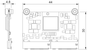
Technical drawing and tolerances for Wireless Wheel 2 Module footprint
Wireless Wheel 2 Module footprint and tolerances (.pdf)
Eagle library[edit | edit source]
The Eagle footprint is designed to be used with TE 1-2199119-x M.2 connector. If any other M.2 connector is used, the footprint must be corrected, as the location pins under the M.2 connector are not identical between different manufacturers and models!
Eagle library of Wireless Wheel 2 Module
3D-model[edit | edit source]
Wireless Wheel 2 Module 3D model file (.step)
Availability[edit | edit source]
Simucube Wireless Wheel 2 modules are sold to commercial sim racing steering wheel manufacturers. Contact sales@granitedevices.com for any enquiries.
