Difference between revisions of "Dead-time distortion"
| [checked revision] | [checked revision] |
m (Text replacement - "{{param|PWM}}" to "PWM") |
|||
| (24 intermediate revisions by 5 users not shown) | |||
| Line 1: | Line 1: | ||
| − | Dead time distortion (DTD) is | + | Dead time distortion (DTD) is a type of cross-over distortion caused by dead-time state of PWM power stages. The problem is present in all [[PWM]] output drives. The longer dead time used, the more significant distortion becomes. |
| + | ==About dead-time== | ||
| + | Dead-time is a blanking time period (upper & lower transistors in off-state simultaneously) of half-bridge power stage. Both transistors are switched off for short period of time to prevent both transistors conducting simultaneously thus causing a short circuit from supply to ground. | ||
| − | == | + | ==Distortion phenomenon== |
| − | [[File:Deadtime schematics freescale.png| | + | [[File:Deadtime schematics freescale.png|500px|thumb|Dead time distortion explanation]] |
Dead time distortion is present in some extent in all half-bridge topology PWM power outputs. | Dead time distortion is present in some extent in all half-bridge topology PWM power outputs. | ||
Description of the image: | Description of the image: | ||
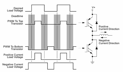
# Schematic: typical single phase half-bridge PWM power output consisting two transistors and an inductive load (inductor). In 3 phase motor drives there are 3 pcs of this kind of circuits excluding inductor (which is replaced by a motor coil). | # Schematic: typical single phase half-bridge PWM power output consisting two transistors and an inductive load (inductor). In 3 phase motor drives there are 3 pcs of this kind of circuits excluding inductor (which is replaced by a motor coil). | ||
| − | # Desired load voltage waveform: the distortion free waveform [[ | + | # Desired load voltage waveform: the distortion free waveform [[setpoint signal]] on load that we would want to see. |
# PWM to top transistor: PWM signal that is controls when the top side transistor is in conductive state. | # PWM to top transistor: PWM signal that is controls when the top side transistor is in conductive state. | ||
# PWM to bottom transistor: PWM signal that is controls when the bottom side transistor is in conductive state. | # PWM to bottom transistor: PWM signal that is controls when the bottom side transistor is in conductive state. | ||
| − | # Grey areas: time when neither of | + | # Grey areas: dead-time when neither of transistors are in conducting state and during this time current will free-wheel thru diodes. Dead-time is necessary to prevent on-state overlapping and shoot-through currents from V+ to GND. |
# Positive current load voltage: this is the achieved (distorted) PWM signal on load when current direction is positive in load inductor. | # Positive current load voltage: this is the achieved (distorted) PWM signal on load when current direction is positive in load inductor. | ||
# Negative current load voltage: this is the achieved (distorted) PWM signal on load when current direction is negative in load inductor. | # Negative current load voltage: this is the achieved (distorted) PWM signal on load when current direction is negative in load inductor. | ||
| Line 17: | Line 19: | ||
==Distortion effects== | ==Distortion effects== | ||
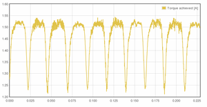
| − | [[File:Torqueripple w deadtime distortion.png|300px|thumb|Measured torque ripple as function of time when motor is rotating. Torque [[ | + | [[File:Torqueripple w deadtime distortion.png|300px|thumb|Measured torque ripple as function of time when motor is rotating. Torque [[setpoint signal|setpoint]] was constant so in ideal case this curve would be flat but instead it shows significant drops in torque periodically. No DTD distortion correction was used.]] |
| − | Some of most notable problems caused by DTD: | + | Some of most notable motion control problems caused by DTD: |
| − | * | + | * Unwanted ripple in torque that may reduce motion smoothness |
| − | * Causes "electrical backlash" or laziness | + | * Causes "electrical backlash" or laziness on motor control. With DTD, motor reaction time is increased whenever current direction is reversed (such as motor is reversing direction). This increases tracking error of servo motor. |
| − | * More difficulty in | + | * More difficulty in servo tuning |
| − | * Reduced servo stiffness. | + | * Reduced servo stiffness |
| + | |||
| + | DTD does not limit to motion control. For example it also affects class D audio amplifiers. [http://en.wikipedia.org/wiki/Class-D_amplifier#Design_challenges] | ||
==Measurements== | ==Measurements== | ||
| − | === | + | {{multiple image |
| − | + | | align = left | |
| + | | direction = vertical | ||
| + | | width = 300 | ||
| + | |||
| + | | image1 = Currentripple w deadtime distortion.png | ||
| + | | alt1 = Before dead time correction | ||
| + | | caption1 = No distortion correction. Top graph: phase current setpoint and achieved current. Bottom graph: PWM duty cycle setpoint | ||
| + | |||
| + | | image2 = Currentripple w deadtime correction2.png | ||
| + | | alt2 = After dead time correction | ||
| + | | caption2 = [[Argon (servo drive)]] distortion correction enabled. Top graph: phase current setpoint and achieved current. Bottom graph: PWM duty cycle setpoint | ||
| + | }} | ||
| + | ===Dead time distortion=== | ||
| + | |||
These graphs show actual distortion on sinusoidal motor currents when [[PWM]] frequency was 17.5 kHz and dead-time length 2 µs. No countermeasures were taken to reduce distortion. | These graphs show actual distortion on sinusoidal motor currents when [[PWM]] frequency was 17.5 kHz and dead-time length 2 µs. No countermeasures were taken to reduce distortion. | ||
| − | Notice how PWM duty cycle | + | Notice the current dips in otherwise sinusoidal signal. There are 6 dips per sine cycle because in this experiment the test was done on a 3 phase motor which has 3 sine currents with 60 degree phase angle differences. Only one phase is displayed but distortion of two remaining phases will induce dips also in the neighbor phases. |
| − | === | + | |
| − | + | Also notice how PWM duty cycle setpoint from drive [[Torque controller|torque/current controller]] jumps up/down trying to compensate dead time errors. However, no current controller alone is fast enough to completely eliminate current ripples. | |
| − | + | ||
| + | ===Distortion elimination=== | ||
| + | The bottom image shows the exactly same experiment with the one above but this time [[Argon (servo drive)]] dead time correction was turned on. Notice how dips almost completely disappear and PWM duty cycle setpoint shows more sine-like waveform. | ||
[[Category:Technology]] | [[Category:Technology]] | ||
| − | [[Category: | + | [[Category:Glossary]] |
| + | [[Category:Argon features]] | ||
Latest revision as of 19:55, 28 August 2015
Dead time distortion (DTD) is a type of cross-over distortion caused by dead-time state of PWM power stages. The problem is present in all PWM output drives. The longer dead time used, the more significant distortion becomes.
Contents
About dead-time[edit | edit source]
Dead-time is a blanking time period (upper & lower transistors in off-state simultaneously) of half-bridge power stage. Both transistors are switched off for short period of time to prevent both transistors conducting simultaneously thus causing a short circuit from supply to ground.
Distortion phenomenon[edit | edit source]
Dead time distortion is present in some extent in all half-bridge topology PWM power outputs.
Description of the image:
- Schematic: typical single phase half-bridge PWM power output consisting two transistors and an inductive load (inductor). In 3 phase motor drives there are 3 pcs of this kind of circuits excluding inductor (which is replaced by a motor coil).
- Desired load voltage waveform: the distortion free waveform setpoint signal on load that we would want to see.
- PWM to top transistor: PWM signal that is controls when the top side transistor is in conductive state.
- PWM to bottom transistor: PWM signal that is controls when the bottom side transistor is in conductive state.
- Grey areas: dead-time when neither of transistors are in conducting state and during this time current will free-wheel thru diodes. Dead-time is necessary to prevent on-state overlapping and shoot-through currents from V+ to GND.
- Positive current load voltage: this is the achieved (distorted) PWM signal on load when current direction is positive in load inductor.
- Negative current load voltage: this is the achieved (distorted) PWM signal on load when current direction is negative in load inductor.
As it figure shows, actual output voltage differs from desired load voltage. Actual PWM duty cycle either becomes higher or lower than desired and distortion direction changes whenever current direction reverses.
Distortion effects[edit | edit source]

Some of most notable motion control problems caused by DTD:
- Unwanted ripple in torque that may reduce motion smoothness
- Causes "electrical backlash" or laziness on motor control. With DTD, motor reaction time is increased whenever current direction is reversed (such as motor is reversing direction). This increases tracking error of servo motor.
- More difficulty in servo tuning
- Reduced servo stiffness
DTD does not limit to motion control. For example it also affects class D audio amplifiers. [1]
Measurements[edit | edit source]
Dead time distortion[edit | edit source]
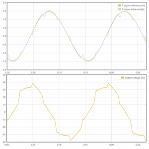
These graphs show actual distortion on sinusoidal motor currents when PWM frequency was 17.5 kHz and dead-time length 2 µs. No countermeasures were taken to reduce distortion.
Notice the current dips in otherwise sinusoidal signal. There are 6 dips per sine cycle because in this experiment the test was done on a 3 phase motor which has 3 sine currents with 60 degree phase angle differences. Only one phase is displayed but distortion of two remaining phases will induce dips also in the neighbor phases.
Also notice how PWM duty cycle setpoint from drive torque/current controller jumps up/down trying to compensate dead time errors. However, no current controller alone is fast enough to completely eliminate current ripples.
Distortion elimination[edit | edit source]
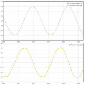
The bottom image shows the exactly same experiment with the one above but this time Argon (servo drive) dead time correction was turned on. Notice how dips almost completely disappear and PWM duty cycle setpoint shows more sine-like waveform.


