Difference between revisions of "Troubleshooting VSD-E/XE disabled state"
| [checked revision] | [checked revision] |
| (4 intermediate revisions by the same user not shown) | |||
| Line 9: | Line 9: | ||
==How enable/disable works== | ==How enable/disable works== | ||
| − | VSD-E/XE has configurable I/O pins in the CMD connector. User may choose any of the pins to act as enable input and also polarity of signal can be selected (inverted/non-inverted). When using VSDEPI, the correct choice as disable input is "Analog input 2 as digital input" with inverted setting. | + | VSD-E/XE has configurable I/O pins in the CMD connector. User may choose any of the pins to act as enable input and also polarity of signal can be selected (inverted/non-inverted). When using VSDEPI, the correct choice as disable input is "Analog input 2 as digital input" with inverted setting. When voltage on analog input 2 is low (or no signal, i.e. disconnected wire), drive is disabled. |
[[VSDEPI]] generates disable-signal that is active low. Disable signal is pulled low by three sources: | [[VSDEPI]] generates disable-signal that is active low. Disable signal is pulled low by three sources: | ||
| Line 16: | Line 16: | ||
*E-stop switch is on (conducting) | *E-stop switch is on (conducting) | ||
| − | If any of above does not request disabled state (parallel port pin 14 = high | + | If any of above does not request disabled state (parallel port pin 14 = high AND chargepump is fed with signal or JP1 inserted AND e-stop is open), then disable signal to drives goes high and drives are enabled. |
===Checking VSDEPI state=== | ===Checking VSDEPI state=== | ||
VSDEPI has several test points on PCB which may be used to analyze the state. To measure state, use DC voltimeter to measure voltage between TP_GND and TP_xxx: | VSDEPI has several test points on PCB which may be used to analyze the state. To measure state, use DC voltimeter to measure voltage between TP_GND and TP_xxx: | ||
| Line 23: | Line 23: | ||
;TP_CPUMP | ;TP_CPUMP | ||
:Chargepump state, when voltage on this is low (<1.5V) chargepump is either happy with chargepump signal or JP1 is inserted | :Chargepump state, when voltage on this is low (<1.5V) chargepump is either happy with chargepump signal or JP1 is inserted | ||
| + | |||
| + | To undestand inner workings of VSDEPI, see [[Media:Vsdepi v1.1 schematics.pdf|VSDEPI board full schematics]]. | ||
==Failsafe method== | ==Failsafe method== | ||
| − | In some cases making it work is found impossible due to incompatibility of PC parallel port. In such cases the remaining option is to | + | In some cases making it work is found impossible due to incompatibility of PC parallel port. In such cases the remaining option is to change disable signal polarity of drives so that drives become always enabled (not able to disabled from controller). |
Connect to drive, import settings and find the disable input settings from GDtool. Pay attention to whether input is currently inverted or non-inverted: | Connect to drive, import settings and find the disable input settings from GDtool. Pay attention to whether input is currently inverted or non-inverted: | ||
| Line 31: | Line 33: | ||
[[File:Gdtool disableinverted.png]] | [[File:Gdtool disableinverted.png]] | ||
| − | Click Configure, select same input (in this case "Analog in 2 as digital input"), choose it and make opposite setting to Inverted checkbox: | + | Click Configure, select same input (in this case "Analog in 2 as digital input"), choose it and make opposite setting to Inverted checkbox (if it was originally inverted, set it non-inverted and vice versa): |
[[File:Gdtool disableinchange.png]] | [[File:Gdtool disableinchange.png]] | ||
Latest revision as of 13:32, 2 September 2014
In some cases combination of VSD-E/XE, VSDEPI and CNC controller exhibits a problem that drive stays in disabled state (blue led blinking). The reason for this is that enable/disable signal is not getting into drives possible caused by various reasons.
In such case, the primary solution is to try fix setup so that enable/disable signal is correctly passed to drives. For this, refer to VSDEPI manual and it's troubleshooting section. Check list:
- Ensure correct pin setup on control software
- Ensure that VSDEPI settings are loaded to drive with GDTool
- Ensure that only 16 pin flat ribbon cable is connected to drive, no USB cable should be present simultaneously
- Try using different parallel port modes from computer BIOS
- Ensure that chargepump works, or try disabling it on VSDEPI
How enable/disable works[edit | edit source]
VSD-E/XE has configurable I/O pins in the CMD connector. User may choose any of the pins to act as enable input and also polarity of signal can be selected (inverted/non-inverted). When using VSDEPI, the correct choice as disable input is "Analog input 2 as digital input" with inverted setting. When voltage on analog input 2 is low (or no signal, i.e. disconnected wire), drive is disabled.
VSDEPI generates disable-signal that is active low. Disable signal is pulled low by three sources:
- Disable input from parallel port is low (pin 14)
- Chargepump signal is not present, VSDEPI internal circuit pulls disable low unless chargepump function is deactivated by inserting jumper JP1.
- E-stop switch is on (conducting)
If any of above does not request disabled state (parallel port pin 14 = high AND chargepump is fed with signal or JP1 inserted AND e-stop is open), then disable signal to drives goes high and drives are enabled.
Checking VSDEPI state[edit | edit source]
VSDEPI has several test points on PCB which may be used to analyze the state. To measure state, use DC voltimeter to measure voltage between TP_GND and TP_xxx:
- TP_ENA
- This is the final disable signal going to drives, when high (4-5VDC) drives are commanded to be enabled
- TP_CPUMP
- Chargepump state, when voltage on this is low (<1.5V) chargepump is either happy with chargepump signal or JP1 is inserted
To undestand inner workings of VSDEPI, see VSDEPI board full schematics.
Failsafe method[edit | edit source]
In some cases making it work is found impossible due to incompatibility of PC parallel port. In such cases the remaining option is to change disable signal polarity of drives so that drives become always enabled (not able to disabled from controller).
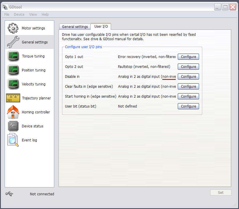
Connect to drive, import settings and find the disable input settings from GDtool. Pay attention to whether input is currently inverted or non-inverted:
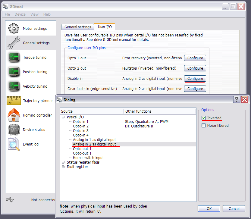
Click Configure, select same input (in this case "Analog in 2 as digital input"), choose it and make opposite setting to Inverted checkbox (if it was originally inverted, set it non-inverted and vice versa):
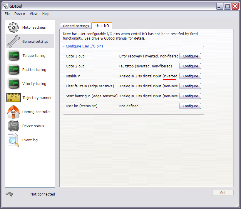
Click ok and verify that line looks like before except inversion setting is now the opposite:
After this, click Set, choose Device->Save active settings in drive. Then unplug USB, connect back to VSDEPI and enjoy!


