Difference between revisions of "Testing of drive IO pins"
From Granite Devices Knowledge Wiki
| [checked revision] | [checked revision] |
| (3 intermediate revisions by the same user not shown) | |||
| Line 1: | Line 1: | ||
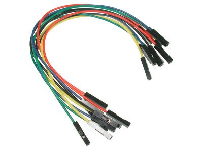
| − | + | [[File:45030-dscn0628.jpg|thumb|Jumper wires that are useful in this testing method]]In cases a signal is not correctly getting through to drive (such as direction signal in step/dir mode), there is a way to test if the problem lies within the drive or exernal circuity. This page describes by example how to test Direction input of drive. | |
==Procedure for differential inputs== | ==Procedure for differential inputs== | ||
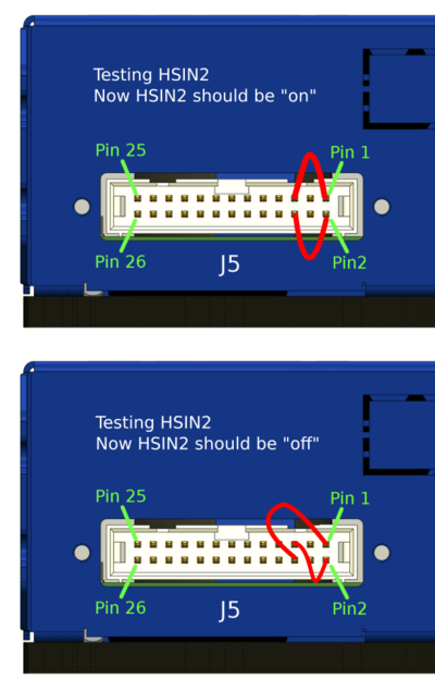
Step 1. Disconnect any cable from I/O connector and use jumper wires to connect the GND and 5V to pins under test. In this case we test HSIN2 by following wiring: | Step 1. Disconnect any cable from I/O connector and use jumper wires to connect the GND and 5V to pins under test. In this case we test HSIN2 by following wiring: | ||
| Line 5: | Line 5: | ||
Step 2. Connect to drive with Granity software and inspect status of the HSIN2 from Testing page status information. | Step 2. Connect to drive with Granity software and inspect status of the HSIN2 from Testing page status information. | ||
| − | If all worked correctly, pin state should have changed in Granity. If pin state is stuck, check connections. If still no luck, it is possible that input pin of device has been damaged. | + | Step 3. Analyze. If all worked correctly, pin state should have changed in Granity. If pin state is stuck, check connections. If still no luck, it is possible that input pin of device has been damaged. If signal state changes as expected, then the error is not in the drive, but probably in the wiring or source of the signal. |
| + | |||
{{tip|This method works also for analog inputs. Instead, just check analog readings of inputs from Granity. You should see +5V or -5V in this test.}} | {{tip|This method works also for analog inputs. Instead, just check analog readings of inputs from Granity. You should see +5V or -5V in this test.}} | ||
Latest revision as of 13:49, 2 October 2015
In cases a signal is not correctly getting through to drive (such as direction signal in step/dir mode), there is a way to test if the problem lies within the drive or exernal circuity. This page describes by example how to test Direction input of drive.Procedure for differential inputs[edit | edit source]
Step 1. Disconnect any cable from I/O connector and use jumper wires to connect the GND and 5V to pins under test. In this case we test HSIN2 by following wiring:
Step 2. Connect to drive with Granity software and inspect status of the HSIN2 from Testing page status information.
Step 3. Analyze. If all worked correctly, pin state should have changed in Granity. If pin state is stuck, check connections. If still no luck, it is possible that input pin of device has been damaged. If signal state changes as expected, then the error is not in the drive, but probably in the wiring or source of the signal.
| This method works also for analog inputs. Instead, just check analog readings of inputs from Granity. You should see +5V or -5V in this test. |
| For single ended input (ones found in IONI for example), just connect the input with single wire to either 5V or GND. |

