Difference between revisions of "VSD-E/XE grounding"
From Granite Devices Knowledge Wiki
| [checked revision] | [checked revision] |
(Created page with "Internal power and ground connections of VSD-E and XE Category:Hardware Category:Setup guides") |
|||
| (2 intermediate revisions by 2 users not shown) | |||
| Line 1: | Line 1: | ||
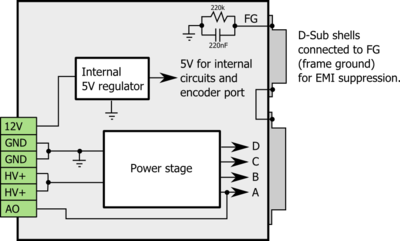
[[File:VSDE grounding scheme.png|thumb|Internal power and ground connections of VSD-E and XE]] | [[File:VSDE grounding scheme.png|thumb|Internal power and ground connections of VSD-E and XE]] | ||
| − | [[ | + | [[VSD-E and VSD-XE]] internal power wiring illustrated. |
| − | [[Category: | + | ;Signals |
| + | * A,B,C and D - the motor output phases | ||
| + | * GND - ground or 0V potential | ||
| + | * FG - frame ground (cable shields connect here) | ||
| + | * 12V - logic supply voltage | ||
| + | * HV+ - high voltage supply of 12-160VDC | ||
| + | ==Frame ground== | ||
| + | FG is internally connected to GND via RC circuit. The capacitor in the circuit passes high frequency interference to ground and resistor prevents static voltage build-up. | ||
| + | [[Category:VSD-E/XE user guide]] | ||
Latest revision as of 22:00, 9 August 2013
VSD-E and VSD-XE internal power wiring illustrated.
- Signals
- A,B,C and D - the motor output phases
- GND - ground or 0V potential
- FG - frame ground (cable shields connect here)
- 12V - logic supply voltage
- HV+ - high voltage supply of 12-160VDC
Frame ground[edit | edit source]
FG is internally connected to GND via RC circuit. The capacitor in the circuit passes high frequency interference to ground and resistor prevents static voltage build-up.
