Difference between revisions of "Testing input pins on VSD-E/XE"
From Granite Devices Knowledge Wiki
| [checked revision] | [checked revision] |
| (6 intermediate revisions by 2 users not shown) | |||
| Line 3: | Line 3: | ||
'''Note:''' | '''Note:''' | ||
This testing method works only for following inputs: | This testing method works only for following inputs: | ||
| − | * | + | * Opto-in 1 |
| − | * | + | * Opto-in 2 |
* Analog in 1 (as digital input) | * Analog in 1 (as digital input) | ||
* Analog in 2 (as digital input) | * Analog in 2 (as digital input) | ||
| − | + | Opto-in 3-4 can't be tested this way because these are shared with serial traffic and would interfere with GDtool connection. However, working GDtool connection proves that inputs 3-4 are working because connection wouldn't be possible otherwise. | |
==Setup== | ==Setup== | ||
Connect drive to GDtool and follow the instructions below. | Connect drive to GDtool and follow the instructions below. | ||
| + | |||
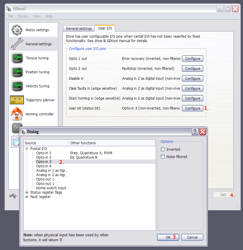
[[File:VSDtestInput1.png]] | [[File:VSDtestInput1.png]] | ||
# Configure "User bit" | # Configure "User bit" | ||
| Line 23: | Line 24: | ||
'''Note:''' this method doesn't verify fast toggling signals. Status page update interval is 1-2 seconds so shorter than 2 second pulses may not change status color. | '''Note:''' this method doesn't verify fast toggling signals. Status page update interval is 1-2 seconds so shorter than 2 second pulses may not change status color. | ||
| − | [[Category: | + | |
| + | [[Category:VSD-E/XE troubleshooting]] | ||
Latest revision as of 22:11, 9 August 2013
This article describes an easy method to verify CMD port input signal proper functionality on VSD-E/XE drives.
Note: This testing method works only for following inputs:
- Opto-in 1
- Opto-in 2
- Analog in 1 (as digital input)
- Analog in 2 (as digital input)
Opto-in 3-4 can't be tested this way because these are shared with serial traffic and would interfere with GDtool connection. However, working GDtool connection proves that inputs 3-4 are working because connection wouldn't be possible otherwise.
Setup[edit | edit source]
Connect drive to GDtool and follow the instructions below.
- Configure "User bit"
- Select input to be tested from configuration dialog
- Click Ok
- Click Set
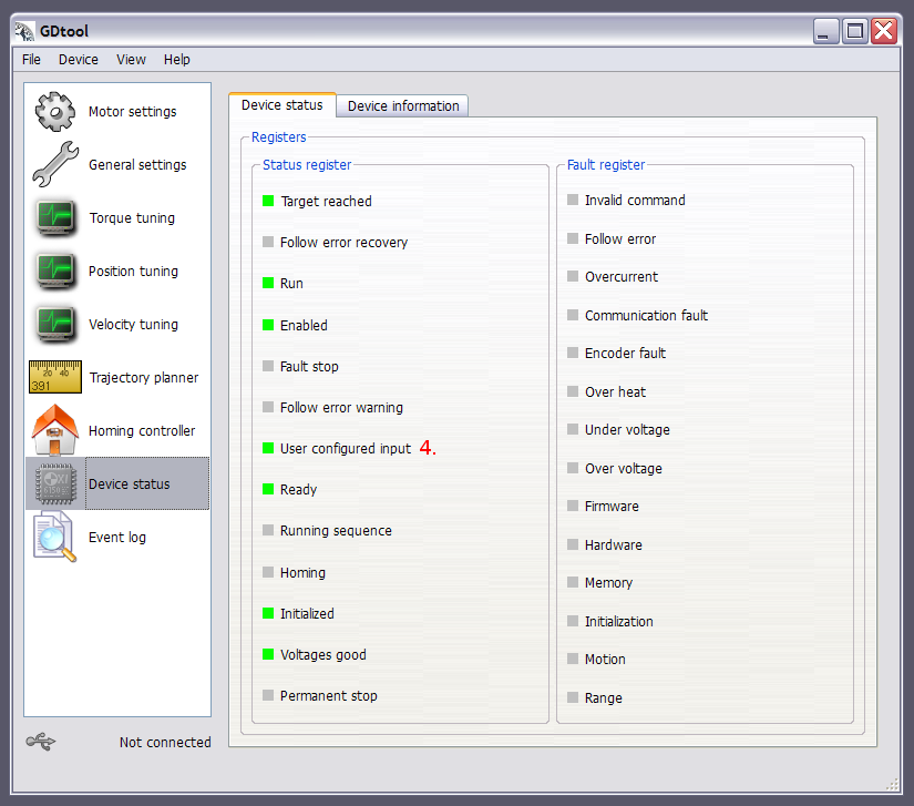
Then go to Device status tab
- 4. Monitor "User configured input" status bit and see if it changes as you toggle the selected input signal on CMD port. Green means that drive reads input value as logic 1 (or 0 if invert option selected).
Note: this method doesn't verify fast toggling signals. Status page update interval is 1-2 seconds so shorter than 2 second pulses may not change status color.

