Difference between revisions of "Template:EncoderPinoutD15"
From Granite Devices Knowledge Wiki
| [checked revision] | [checked revision] |
| (3 intermediate revisions by one other user not shown) | |||
| Line 25: | Line 25: | ||
| 10|| class="powpin" |GND || colspan="6" | Encoder supply ground | | 10|| class="powpin" |GND || colspan="6" | Encoder supply ground | ||
|- | |- | ||
| − | | 11|| class="inpin" |GPI3|| colspan="3" | Axis negative direction end limit switch (optional). | + | | 11|| class="inpin" |GPI3|| colspan="3" | Axis negative direction end limit switch (optional). Normally closed (NC) switch is highly recommended for safety reasons.<br /> Connect it between this pin and GND pin. Normally open (NO) switch can be used, and the switch polarity can be changed with {{param|LSP}}. || Clock/MA- || Clock- || CLK |
|- | |- | ||
| − | | 12|| class="inpin" |GPI2|| colspan="3" | Axis positive direction end limit switch (optional). | + | | 12|| class="inpin" |GPI2|| colspan="3" | Axis positive direction end limit switch (optional).Normally closed (NC) switch is highly recommended for safety reasons.<br /> Connect it between this pin and GND pin. Normally open (NO) switch can be used, and the switch polarity can be changed with {{param|LSP}}. || Clock/MA+ || Clock+ || CSn |
|- | |- | ||
| − | | 13|| class="inpin" |GPI1|| colspan="5" | Axis home switch switch (optional). | + | | 13|| class="inpin" |GPI1|| colspan="5" | Axis home switch switch (optional). Normally closed (NC) switch is highly recommended for safety reasons.<br /> Connect it between this pin and GND pin. Normally open (NO) switch can be used, and the switch polarity can be changed with {{param|HMS}}. || DO |
|- | |- | ||
| 14|| class="inpin" |C-|| Differential input C- || Index channel Z- || Index channel Z+ || Data/SLO- || Data- || - | | 14|| class="inpin" |C-|| Differential input C- || Index channel Z- || Index channel Z+ || Data/SLO- || Data- || - | ||
Latest revision as of 12:57, 9 October 2020
| Pin # | Pin name | Electrical type (in most feedback device modes) | Quadrature encoder | SinCos encoder | BiSS-C encoder | SSI encoder | AMS SSI encoder |
|---|---|---|---|---|---|---|---|
| Shell | GND | Earth/case | |||||
| 1 | HALL_W | Hall sensor digital input, phase W | - | - | - | ||
| 2 | HALL_V | Hall sensor digital input, phase V | - | - | - | ||
| 3 | HALL_U | Hall sensor digital input, phase U | - | - | - | ||
| 4 | GND | Encoder supply ground | |||||
| 5 | B- | Differential input B- | Channel B- | SinCos input B- | - | - | - |
| 6 | B+ | Differential input B+ | Channel B+ | SinCos input B+ | - | - | - |
| 7 | A- | Differential input A- | Channel A- | SinCos input A- | - | - | - |
| 8 | A+ | Differential input A+ | Channel A+ | SinCos input A+ | - | - | - |
| 9 | 5V_OUT | Encoder supply 5V output | |||||
| 10 | GND | Encoder supply ground | |||||
| 11 | GPI3 | Axis negative direction end limit switch (optional). Normally closed (NC) switch is highly recommended for safety reasons. Connect it between this pin and GND pin. Normally open (NO) switch can be used, and the switch polarity can be changed with Limit switch polarityLSP. |
Clock/MA- | Clock- | CLK | ||
| 12 | GPI2 | Axis positive direction end limit switch (optional).Normally closed (NC) switch is highly recommended for safety reasons. Connect it between this pin and GND pin. Normally open (NO) switch can be used, and the switch polarity can be changed with Limit switch polarityLSP. |
Clock/MA+ | Clock+ | CSn | ||
| 13 | GPI1 | Axis home switch switch (optional). Normally closed (NC) switch is highly recommended for safety reasons. Connect it between this pin and GND pin. Normally open (NO) switch can be used, and the switch polarity can be changed with Home switch or hard stop search direction (Home switch polarity)HMS. |
DO | ||||
| 14 | C- | Differential input C- | Index channel Z- | Index channel Z+ | Data/SLO- | Data- | - |
| 15 | C+ | Differential input C+ | Index channel Z+ | Index channel Z+ | Data/SLO+ | Data+ | - |
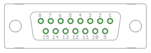
| Pin layout | Female D-sub 15 connector as it appears from outside of drive. Note: counterpart (male) connector has mirrored pin layout if viewed from pin side, and same layout if viewed from soldering side. | ||||||
