Difference between revisions of "Pulse burst positioning"
From Granite Devices Knowledge Wiki
| [checked revision] | [checked revision] |
(→How to use) |
m (Text replacement - "\[\[([A-Z]{2,3})\]\]" to "{{param|$1}}") |
||
| Line 10: | Line 10: | ||
==How to use== | ==How to use== | ||
Pulse burst is the minimalistic yet high performing position setpoint method available. Suitable signal may be generated by various means: | Pulse burst is the minimalistic yet high performing position setpoint method available. Suitable signal may be generated by various means: | ||
| − | * | + | *{{param|PLC}} with at least two digital outputs |
*A simple timer & counter circuit | *A simple timer & counter circuit | ||
*Microcontroller [[GPIO]] pin | *Microcontroller [[GPIO]] pin | ||
| Line 17: | Line 17: | ||
====Drive parameterization==== | ====Drive parameterization==== | ||
In [[Argon]] the following configuration enables burst pulse mode: | In [[Argon]] the following configuration enables burst pulse mode: | ||
| − | *Set | + | *Set {{param|CM}} as Position control |
| − | *Set | + | *Set {{param|CRI}} as Pulse train & direction |
| − | *Set | + | *Set {{param|CAL}} and {{param|CVL}} to your desired acceleration and velocity values |
*Wire J5 connector according to [[Argon_user_guide/J5_connector_electrical_interfacing#Complete_example_with_pulse_.26_direction|this diagram]] | *Wire J5 connector according to [[Argon_user_guide/J5_connector_electrical_interfacing#Complete_example_with_pulse_.26_direction|this diagram]] | ||
Latest revision as of 19:53, 28 August 2015

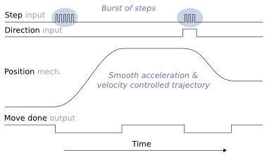
Illustration of input step pulse & direction signals, motor position and move done output as function of time.
Pulse burst positioning is a setpoint method based on pulse and direction signals. In pulse burst mode, controller need only to generate a burst of pulses with direction signal to begin a motion relative to current position. Motion will comply with pre-configured acceleration and velocity limits of the drive.
Contents
Pulse burst positioning properties[edit | edit source]
- Simplicity - easy to understand and implement point-to-point motion
- No real-time pulse train controller needed - smooth motion profile is generated inside the drive
- Exact - setpoint signal path is fully digital
- Change setpoint on the fly - not necessary to wait for motion to finish before sending new pulses
How to use[edit | edit source]
Pulse burst is the minimalistic yet high performing position setpoint method available. Suitable signal may be generated by various means:
- PLC with at least two digital outputs
- A simple timer & counter circuit
- Microcontroller GPIO pin
- Or any programmable device with controllable digital outputs
Practical example[edit | edit source]
Drive parameterization[edit | edit source]
In Argon the following configuration enables burst pulse mode:
- Set Control modeCM as Position control
- Set Setpoint inputCRI as Pulse train & direction
- Set Acceleration limitCAL and Velocity limitCVL to your desired acceleration and velocity values
- Wire J5 connector according to this diagram
Doing incremental move[edit | edit source]
The C-style code below generates the signaling.
void IncrementalMove( int distance )
{
  int i;

  /* set direction output pin */
  if(distance<0)
    SetDirectionOutputPin(0);
  else
    SetDirectionOutputPin(1);

  /* generate step pulses to start motion. quantity of pulses = distance */
  for( i=0; i< abs(distance); i++ )
  {
    Delay_ms(0.001); /* wait 1 microseconds or more */
    SetPulseOutputPin(1);
    Delay_ms(0.001); /* wait 1 microseconds or more */
    SetPulseOutputPin(0);
  }
}
- SetPulseOutputPin sets the digital state of HSIN1 pin on Argon
- SetDirectionOutputPin sets the digital state of HSIN2 pin on Argon
Monitoring when motion is complete[edit | edit source]
Returns true when motion has successfully finished. False if timeout expired or drive faulted.
bool WaitForMoveDone( double timeout )
{
  double waited=0;

  while(waited<timeout)
  {
    if( GetMotionCompletePinState() == true )
      return true; /* motion is now complete, return true*/

    if( GetFaultPinState() == true )
      return false; /* drive is in fault state, return false*/

    /*motion is not complete, wait some time and poll again*/
    Delay_ms(10); /* 0.01 seconds */
    waited=waited+0.01;
  }

  /*return false because timeouted */
  return false;
}
- GetMotionCompletePinState reads the GPO1 pin state from Argon
- GetFaultPinState reads the GPO3 pin state from Argon
Usage example[edit | edit source]
IncrementalMove(500);
WaitForMoveDone();
IncrementalMove(1000);
WaitForMoveDone();
IncrementalMove(-1500);
WaitForMoveDone();