Difference between revisions of "Signal path of motor drive"
From Granite Devices Knowledge Wiki
| [checked revision] | [checked revision] |
m (Tero K moved page Scale of setpoint values to Signal path of motor drive) |
|
(No difference)
| |
Revision as of 12:56, 7 April 2014
In Granite Devices drives the torque, velocity and position limits and setpoints are defined as integer numbers. The vales are represented "hardware" scale which are described below.
Setpoint signal path
Setpoint signal path converts user setpoint to internal setpoint.
Setpoint signal path
Main parts are:
- Input multiplier. Purpose of this is to increase resolution of input setpoint to allow more fine grained velocity & acceleration control in trajectory planner. By default MUL value is 50.
- Setpoint smoothing filter. If enabled, applies low pass filter to signal reducing jitter and roughness of signal but also introduces about some delay. By default the filter has 100% attenuation at 250Hz.
- Trajectory planner. This limits rate of change of setpoint signal based on CVL and CAL parameters. Output rate maximum rate of change:
- Velocity changes max CAL nubmer of units per control cycle (control cycle is 400µs in most GD drives)
- Velocity maximum value is limited to CVL
- Input divider. This divides setpoint signal by DIV to give desired output scale for internal setpoint. Combination of multiplier and divider can be used change total scaling of setpoint signal.
Internal setpoint
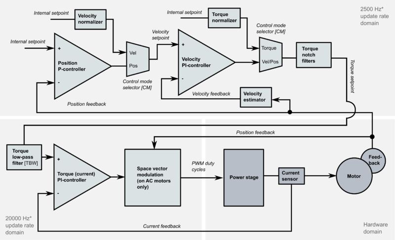
Internal setpoint equals the scale of feedback signals in position and velocity modes. The scale of feedback signals are:
- Position feedback: position sensor counter raw value
- Velocity feedback: number of feedback device counts per one control cycle. Obtained by calculating the difference of position feedback values at every control cycle.
- Torque: hardware specific scale, however Torque scaler knows the hardware scale and scales internal setpoint so that value of +/-16384 represents full torque scale (i.e. internal setpoint value 16384 outputs configured peak current MMC and 8192 outputs MMC/2)
Controller
The default controller type of GD drives is cascaded type where each controlled variable has it's own PI or P controller. In position mode such structure is called as PIV controller.

