Difference between revisions of "3-level PWM vs 2-level PWM"
| [checked revision] | [checked revision] |
(→Simulated waveforms) |
|||
| Line 8: | Line 8: | ||
:The output of 3-level PWM are in-phase with each other which yields three distinct voltage levels of voltage differential over the load. The third voltage level is ''zero voltage'' which features lower current rate of change in the coil yielding lower total current ripple. | :The output of 3-level PWM are in-phase with each other which yields three distinct voltage levels of voltage differential over the load. The third voltage level is ''zero voltage'' which features lower current rate of change in the coil yielding lower total current ripple. | ||
==Simulated waveforms== | ==Simulated waveforms== | ||
| + | These simulations display a case where one coil is being driven with 2 and 3 level PWMs. All simulation parameters are kept same, only difference is the switching scheme. | ||
===2-level PWM=== | ===2-level PWM=== | ||
[[File:Pwm2level m.PNG]] | [[File:Pwm2level m.PNG]] | ||
===3-level PWM=== | ===3-level PWM=== | ||
[[File:Pwm3level m.PNG]] | [[File:Pwm3level m.PNG]] | ||
| + | |||
==Effects== | ==Effects== | ||
While 3 level PWM may require more sophisticated control circuity, it gives benefits of notably reduced ripple current which has benefits such as reduced motor heat dissipation and longer motor bearing life. Current ripple directly relates wearing bearings due to eddy currents in metallic materials. | While 3 level PWM may require more sophisticated control circuity, it gives benefits of notably reduced ripple current which has benefits such as reduced motor heat dissipation and longer motor bearing life. Current ripple directly relates wearing bearings due to eddy currents in metallic materials. | ||
Revision as of 23:08, 8 July 2014
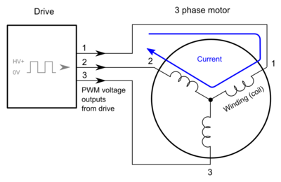
Typical motor drive based controls motor coil current by outputting PWM signal which is basically high frequency on/off switching of HV DC bus voltage. Switching voltage on and off yields low heat dissipation from drive compared to linear amplifier designs. Typical PWM based drive typically operates around 90% power conversion efficiency while linear amplifiers rarely operate above 50% efficiency.
PWM switching schemes
In motor control, two most common switching schemes are conventional 2-level a.k.a. antiphase PWM and more modern 3-level PWM.
- 2 level PWM
- The outputs of antiphase or 2-level PWM are inversions of each other. The effective output voltage is the average of voltage differential over inductive load such as motor coil. Coil is driven either full positive or full negative voltage of HV DC bus. Full positive voltage induces maximum current change in positive direction and vice versa. Switching between positive and negative output yields sawtooth like current ripple over coil.
- 3 level PWM
- The output of 3-level PWM are in-phase with each other which yields three distinct voltage levels of voltage differential over the load. The third voltage level is zero voltage which features lower current rate of change in the coil yielding lower total current ripple.
Simulated waveforms
These simulations display a case where one coil is being driven with 2 and 3 level PWMs. All simulation parameters are kept same, only difference is the switching scheme.
2-level PWM
3-level PWM
Effects
While 3 level PWM may require more sophisticated control circuity, it gives benefits of notably reduced ripple current which has benefits such as reduced motor heat dissipation and longer motor bearing life. Current ripple directly relates wearing bearings due to eddy currents in metallic materials.


