Difference between revisions of "Template:EncoderPinoutD15"
From Granite Devices Knowledge Wiki
| [checked revision] | [checked revision] |
| Line 35: | Line 35: | ||
| 15|| class="inpin" | C+|| Differential input C+ || Index channel Z+ || Index channel Z+ || Data/SLO+ || Data+ || - | | 15|| class="inpin" | C+|| Differential input C+ || Index channel Z+ || Index channel Z+ || Data/SLO+ || Data+ || - | ||
|- | |- | ||
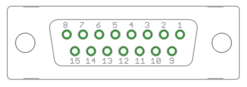
| − | | Pin layout || colspan= | + | | Pin layout || colspan = 7 | Female D-sub 15 connector as it appears from outside of drive. Note: counterpart (male) connector has mirrored pin layout if viewed from pin side, and same layout if viewed from soldering side. |
[[File:d15_pinout.png|frameless|500x500px]] | [[File:d15_pinout.png|frameless|500x500px]] | ||
|} | |} | ||
Revision as of 10:56, 23 April 2018
| Pin # | Pin name | Electrical type (in most feedback device modes) | Quadrature encoder | SinCos encoder | BiSS-C encoder | SSI encoder | AMS SSI encoder |
|---|---|---|---|---|---|---|---|
| Shell | GND | Earth/case | |||||
| 1 | HALL_W | Hall sensor digital input, phase W | - | - | - | ||
| 2 | HALL_V | Hall sensor digital input, phase V | - | - | - | ||
| 3 | HALL_U | Hall sensor digital input, phase U | - | - | - | ||
| 4 | GND | Encoder supply ground | |||||
| 5 | B- | Differential input B- | Channel B- | SinCos input B- | - | - | - |
| 6 | B+ | Differential input B+ | Channel B+ | SinCos input B+ | - | - | - |
| 7 | A- | Differential input A- | Channel A- | SinCos input A- | - | - | - |
| 8 | A+ | Differential input A+ | Channel A+ | SinCos input A+ | - | - | - |
| 9 | 5V_OUT | Encoder supply 5V output | |||||
| 10 | GND | Encoder supply ground | |||||
| 11 | GPI3 | Axis negative direction end limit switch (optional). Connect normally closed (NC) limit switch between this pin and GND pin. | Clock/MA- | Clock- | CLK | ||
| 12 | GPI2 | Axis positive direction end limit switch (optional). Connect normally closed (NC) limit switch between this pin and GND pin. | Clock/MA+ | Clock+ | CSn | ||
| 13 | GPI1 | Axis home switch switch (optional). Connect normally closed (NC) limit switch between this pin and GND pin. | DO | ||||
| 14 | C- | Differential input C- | Index channel Z- | Index channel Z+ | Data/SLO- | Data- | - |
| 15 | C+ | Differential input C+ | Index channel Z+ | Index channel Z+ | Data/SLO+ | Data+ | - |
| Pin layout | Female D-sub 15 connector as it appears from outside of drive. Note: counterpart (male) connector has mirrored pin layout if viewed from pin side, and same layout if viewed from soldering side. | ||||||
