Difference between revisions of "Simucube Wireless Wheel 2"
| [unchecked revision] | [unchecked revision] |
(→Resources) |
|||
| Line 167: | Line 167: | ||
==Resources== | ==Resources== | ||
===Eagle library=== | ===Eagle library=== | ||
| + | [[Media:wireless_wheel_2_eagle_library.pdf|Eagle library of Wireless Wheel 2 Module]] | ||
| + | |||
===3D-model=== | ===3D-model=== | ||
| + | [[Media:Wireless_Wheel_2_Module_3d.zip|Wireless Wheel 2 Module 3D model file (.step)]] | ||
[[Category:Hardware]] | [[Category:Hardware]] | ||
[[Category:Simucube_2]] | [[Category:Simucube_2]] | ||
Revision as of 10:53, 19 August 2021
| Wireless Wheel 2 Module | |
|---|---|
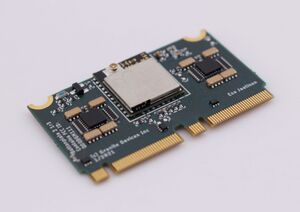
The Simucube Wireless Wheel 2 Module is an upgraded version of the Simucube Wireless wheel module. New module offers more digital inputs, 4 analog axis, in-build battery charger and voltage regulator.
Contents
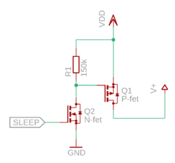
Analog inputs
Wireless module offers AVCC output for analog devices. Output in AVCC is pulsed for lower power consumption and output is on only when the ADC module is sampling inputs. Output pulses are 2ms long and frequency is 100Hz, this means that AVCC is on 20% of the time. 2ms pulses work great with potentiometers, but Hall-effect sensors might not work with pulsed AVCC if Hall-sensor power-on time is too long. One option to provide VCC for Hall-sensor is to power it from Wireless Wheel 2 VDD pin and use MOSFETs connected to SLEEP pin so Hall-sensor can be powered off while Wireless Wheel 2 isn’t connected. SLEEP pin is high when Wireless Wheel 2 is connected to Simucube.
Pinout
Wireless Wheel 2 Module uses M.2 connectors to fit all the I/O pins in compact, low-profile packet packet.
Left M.2 connector
| Bottom side | Top side | ||||
|---|---|---|---|---|---|
| Function | Signal | Pin | Signal | Function | |
| GND | GND | 66 | 67 | AVCC | 3.0 V OUTPUT to analog circuitry Max. 100 mA including VDD current. |
| GND | GND | 64 | 65 | AN0 | ADC CH0 INPUT 0 .. 3.0 V voltage range |
| GND | GND | 62 | 63 | AN1 | ADC CH1 INPUT 0 .. 3.0 V voltage range |
| GND | GND | 60 | 61 | AN2 | ADC CH2 INPUT 0 .. 3.0 V voltage range |
| Input | BTN64 | 58 | 59 | AN3 | ADC CH3 INPUT 0 .. 3.0 V voltage range |
| Input | BTN63 | 56 | 57 | BTN1 | Input |
| Input | BTN62 | 54 | 55 | BTN2 | Input |
| Input | BTN61 | 52 | 53 | BTN3 | Input |
| Input | BTN60 | 50 | 51 | BTN4 | Input |
| Input | BTN89 | 48 | 49 | BTN5 | Input |
| Input | BTN58 | 46 | 47 | BTN6 | Input |
| Input | BTN57 | 44 | 45 | BTN7 | Input |
| Input | BTN56 | 42 | 43 | BTN8 | Input |
| Input | BTN55 | 40 | 41 | BTN9 | Input |
| Input | BTN54 | 38 | 39 | BTN10 | Input |
| Input | BTN53 | 36 | 37 | BTN11 | Input |
| Input | BTN52 | 34 | 35 | BTN12 | Input |
| Input | BTN51 | 32 | 33 | BTN13 | Input |
| Input | BTN50 | 30 | 31 | BTN14 | Input |
| Input | BTN49 | 28 | 29 | BTN15 | Input |
| GND | GND | 26 | 27 | BTN16 | Input |
| Input | BTN80 | 24 | 25 | GND | GND |
| Input | BTN78 | 22 | 23 | BTN79 | Input |
| Input | BTN76 | 20 | 21 | BTN77 | Input |
| Input | BTN74 | 18 | 19 | BTN75 | Input |
| Input | BTN72 | 16 | 17 | BTN73 | Input |
| Input | BTN70 | 14 | 15 | BTN71 | Input |
| Input | BTN68 | 12 | 13 | BTN69 | Input |
| Input | BTN66 | 10 | 11 | BTN67 | Input |
| Input | BTN17 | 8 | 9 | BTN65 | Input |
| Input | BTN19 | 6 | 7 | BTN18 | Input |
| Input | BTN32 | 4 | 5 | LED1 | 3.0 V status LED OUTPUT through 220 Ohm series resistor |
| Input | BTN30 | 2 | 3 | BTN20 | Input |
| - | - | - | 1 | BTN31 | Input |
Right M.2 connector
| Bottom side | Top side | ||||
|---|---|---|---|---|---|
| Function | Signal | Pin | Signal | Function | |
| Input | BTN28 | 66 | 67 | BTN29 | Input |
| Input | BTN26 | 64 | 65 | BTN27 | Input |
| Input | BTN22 | 62 | 63 | BTN25 | Input |
| Input | BTN24 | 60 | 61 | BTN21 | Input |
| Do not connect | - | 58 | 59 | BTN23 | Input |
| Do not connect | - | 56 | 57 | - | Do not connect |
| Input | BTN96 | 54 | 55 | - | Do not connect |
| Input | BTN95 | 52 | 53 | - | Do not connect |
| Input | BTN94 | 50 | 51 | - | Do not connect |
| Input | BTN93 | 48 | 49 | - | Do not connect |
| Input | BTN92 | 46 | 47 | SLEEP | BP2 module sleep status Active LOW (BP2 sleeps) |
| Input | BTN91 | 44 | 45 | TX | LEUART TX signal OUTPUT |
| Input | BTN90 | 42 | 43 | RX | LEUART RX signal INPUT |
| Input | BTN89 | 40 | 41 | LED2 | 2nd indicator LED OUTPUT 3.0 V through 220 Ohm resistor |
| Input | BTN88 | 38 | 39 | PADDLE1 | Paddle input 1 |
| Input | BTN87 | 36 | 37 | PADDLE2 | Paddle input 2 |
| Input | BTN86 | 34 | 35 | GND | GND |
| Input | BTN85 | 32 | 33 | VDD | +3.0 V OUTPUT Max. 100 mA including AVCC current. |
| Input | BTN84 | 30 | 31 | BTN33 | Input |
| Input | BTN83 | 28 | 29 | BTN34 | Input |
| Input | BTN82 | 26 | 27 | BTN35 | Input |
| Input | BTN81 | 24 | 25 | BTN36 | Input |
| GND | GND | 22 | 23 | BTN37 | Input |
| GND | GND | 20 | 21 | BTN38 | Input |
| LED indicator for battery charging Connect LED Anode to BATT |
LED_CHG | 18 | 19 | BTN39 | Input |
| SWITCH_IN operating voltage input | BATT | 16 | 17 | BTN40 | Input |
| BATT | 14 | 15 | BTN41 | Input | |
| LiPO/Ion/battery positive terminal | BATT+ | 12 | 13 | BTN42 | Input |
| BATT+ | 10 | 11 | BTN43 | Input | |
| GND | GND | 8 | 9 | BTN44 | Input |
| GND | 6 | 7 | BTN45 | Input | |
| Voltage INPUT terminal 5.0 V ± 5 % |
VIN | 4 | 5 | BTN46 | Input |
| VIN | 2 | 3 | BTN47 | Input | |
| - | - | - | 1 | BTN48 | Input |
Resources
Eagle library
Eagle library of Wireless Wheel 2 Module

