Difference between revisions of "Tuning position controller"
(Created page with "Position controller tuning means finding the correct drive settings and feedback gain values to achieve a proper Servo stiffness and response to a position Setpoint sign...") |
(No difference)
|
Revision as of 00:00, 27 August 2013
Position controller tuning means finding the correct drive settings and feedback gain values to achieve a proper Servo stiffness and response to a position setpoint change.
Contents
Position control tuning method
TODO Manual tuning of torque controller is some times done in order to optimize the torque controller response or to find the correct motor resistance MR and inductance ML parameters if unknown. Manual tuning also usually yields better torque response than the direct method which may help tuning of velocity or position tuning.
In order to change torque tuning, one needs to change motor resistance MR and inductance ML parameters until the torque response looks satisfactory.
Preparations
Steps to do to begin position tuning:
- Ensure that motor is parameterized correctly and working and torque control tuning has been properly done.
- Attach motor to the target machine in a position where it can rotate in both directions
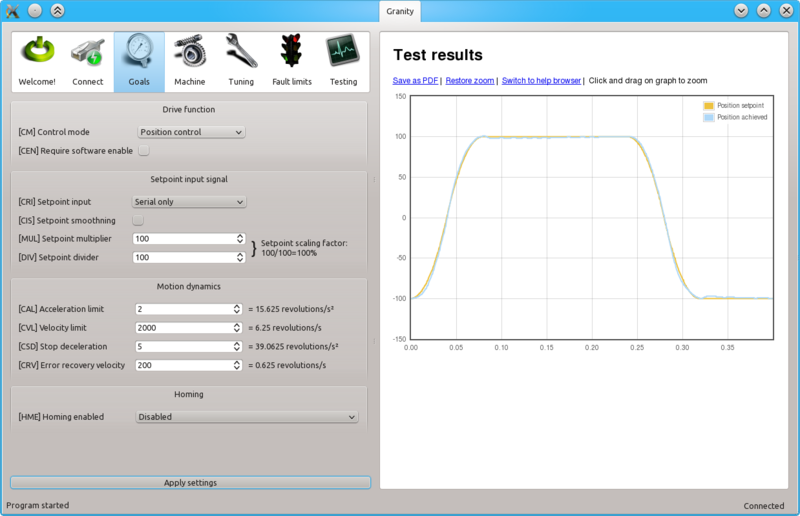
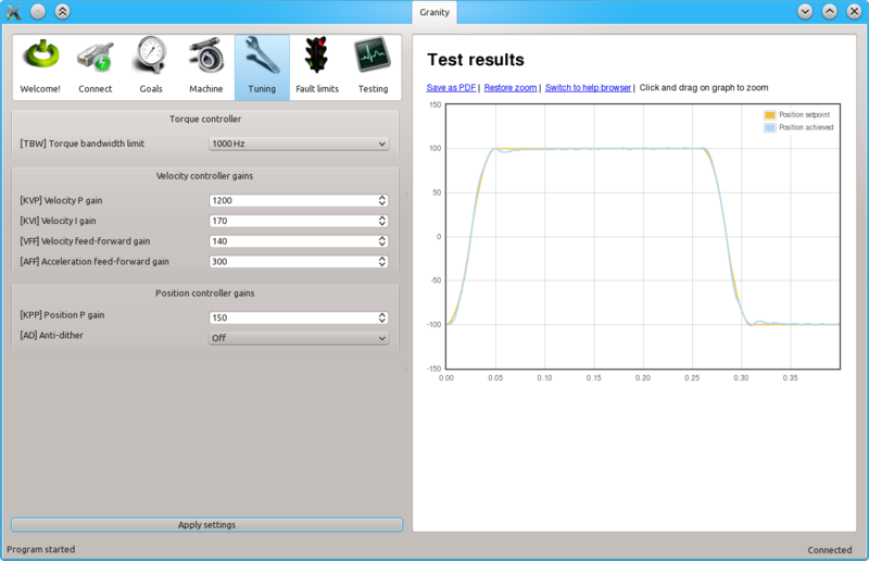
- Make following parameter changes to Granity and click apply afterwards:
- Optional but recommended:
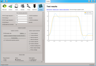
- Set-up the test stimulus and capture settings from Testing tab (an example, may be varied):
- Set target setpoint 1 TSP1 to 100
- Set delay 1 TSD1 to 0.25 seconds
- Set target setpoint 2 TSP2 to -100
- Set delay1 STD2 to 0.25 s
- Choose sample rate TSR of 500 to 2500 Hz
- Choose Capture setpoint change ind positive direction from the dropdown
- Tick Continuously repeating capture
- Tick Position setpoint and Position achieved from signals
- Tick Start capture to begin continous capture.
- Tick Enable test stimulus TSE to begin a continuous position back and forth motion generation
Once the steps above are done, motor should be generating short distance back and forth motion motion and position response graphs should appear on the right side of Granity about once in 3-5 seconds.
Adjusting MR and ML to for optimum torque control
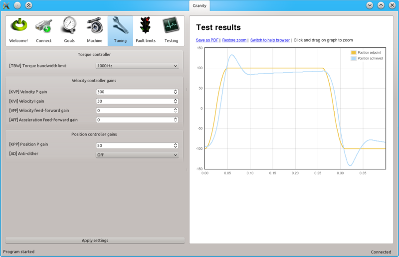
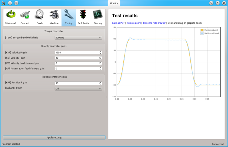
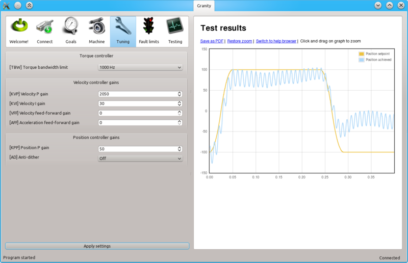
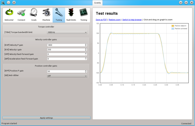
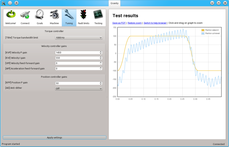
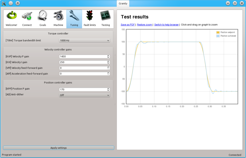
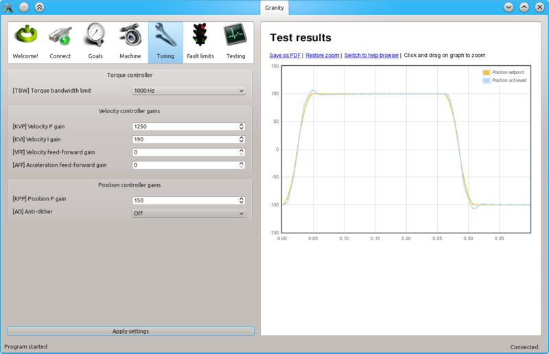
The task here is to adjust the MR and ML parameters to achieve near optimum step response for the torque controller. Observe the images below for guidance.
| If the drive faults during this testing due to overcurrent, try reducing TSP1 value or increase fault current tolerance FOC parameter. Or try radically different MR and ML values. |
Steps to do after manual tuning finished
UPDATE
- Stop test stimulus by unticking TSE
- Stop scope catpure by unticking Continuously repeating capture
- Undo all temporary changes made to settings (such as TBW, CM, DIV, MUL) but leave the optimized MR and ML values active
- Save settings to drive memory by clicking Save settings on drive non-volatile memory button
