Difference between revisions of "IONICUBE connectors and pinouts"
From Granite Devices Knowledge Wiki
| [checked revision] | [checked revision] |
| Line 4: | Line 4: | ||
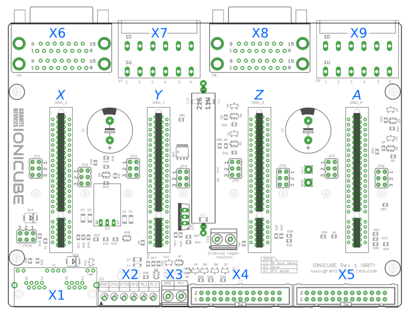
{{picturebox|Ionicubemotorconnectors.png|caption=Names of power and feedback ports. I.e. X9A means upper floor connector of X9 and X9B the lower floor of X9.}} | {{picturebox|Ionicubemotorconnectors.png|caption=Names of power and feedback ports. I.e. X9A means upper floor connector of X9 and X9B the lower floor of X9.}} | ||
{{picturebox|Ionicube x2345.png|caption=A closeup of X2, X3, X4 and X5}} | {{picturebox|Ionicube x2345.png|caption=A closeup of X2, X3, X4 and X5}} | ||
| + | |||
| + | |||
| + | |||
| + | {| class="wikitable" | ||
| + | ! Pin number in header!!Pin number in D25 cable!!Signal name!!Typical usage | ||
| + | |rowspan=14| | ||
| + | !Pin number in header!!Pin number in D25 cable!!Signal name!!Typical usage | ||
| + | |- | ||
| + | | 1||1||ENABLE||Enable all axis (with or without chargepump)||2||14||PWM||[[PWM]] input for VFD analog output | ||
| + | |- | ||
| + | | 3||2||HSIN1_X||Direction input X||4||15||GPO4_A||Limit switch output A | ||
| + | |- | ||
| + | | 5||3||HSIN2_X||Pulse/step input X||6||16||BUFFER_IN1||Controls BUFFER_OUT1 state | ||
| + | |- | ||
| + | | 7||4||HSIN1_Y||Direction input Y||8||17||BUFFER_IN2||Controls BUFFER_OUT2 state | ||
| + | |- | ||
| + | | 9||5||HSIN2_Y||Pulse/step input Y||10||18||GND||rowspan=8|Ground | ||
| + | |- | ||
| + | | 11||6||HSIN1_Z||Direction input Z||12||19||GND | ||
| + | |- | ||
| + | | 13||7||HSIN2_Z||Pulse/step input A||14||20||GND | ||
| + | |- | ||
| + | | 15||8||HSIN1_A||Direction input A||16||21||GND | ||
| + | |- | ||
| + | | 17||9||HSIN2_A||Pulse/step input A||18||22||GND | ||
| + | |- | ||
| + | | 19||10||STOP_OUT||Fault or E-stop (active low)||20||23||GND | ||
| + | |- | ||
| + | | 21||11||GPO4_X||Limit switch output X||22||24||GND | ||
| + | |- | ||
| + | | 23||12||GPO4_Y||Limit switch output Y||24||25||GND | ||
| + | |- | ||
| + | | 25||13||GPO4_Z||Limit switch output Z||26||N/A||Not connected|| | ||
| + | |} | ||
[[category:IONI user guide]] | [[category:IONI user guide]] | ||
[[category:IONICUBE]] | [[category:IONICUBE]] | ||
Revision as of 23:49, 20 March 2015

Names of power and feedback ports. I.e. X9A means upper floor connector of X9 and X9B the lower floor of X9.
| Pin number in header | Pin number in D25 cable | Signal name | Typical usage | Pin number in header | Pin number in D25 cable | Signal name | Typical usage | |
|---|---|---|---|---|---|---|---|---|
| 1 | 1 | ENABLE | Enable all axis (with or without chargepump) | 2 | 14 | PWM | PWM input for VFD analog output | |
| 3 | 2 | HSIN1_X | Direction input X | 4 | 15 | GPO4_A | Limit switch output A | |
| 5 | 3 | HSIN2_X | Pulse/step input X | 6 | 16 | BUFFER_IN1 | Controls BUFFER_OUT1 state | |
| 7 | 4 | HSIN1_Y | Direction input Y | 8 | 17 | BUFFER_IN2 | Controls BUFFER_OUT2 state | |
| 9 | 5 | HSIN2_Y | Pulse/step input Y | 10 | 18 | GND | Ground | |
| 11 | 6 | HSIN1_Z | Direction input Z | 12 | 19 | GND | ||
| 13 | 7 | HSIN2_Z | Pulse/step input A | 14 | 20 | GND | ||
| 15 | 8 | HSIN1_A | Direction input A | 16 | 21 | GND | ||
| 17 | 9 | HSIN2_A | Pulse/step input A | 18 | 22 | GND | ||
| 19 | 10 | STOP_OUT | Fault or E-stop (active low) | 20 | 23 | GND | ||
| 21 | 11 | GPO4_X | Limit switch output X | 22 | 24 | GND | ||
| 23 | 12 | GPO4_Y | Limit switch output Y | 24 | 25 | GND | ||
| 25 | 13 | GPO4_Z | Limit switch output Z | 26 | N/A | Not connected |


