|
|
| Line 6: |
Line 6: |
| | *Fault tolerant | | *Fault tolerant |
| | *Availability of parts | | *Availability of parts |
| | + | *Any motor supply voltage possible |
| | || | | || |
| | *Switching PSUs typically don't allow temporary overloading | | *Switching PSUs typically don't allow temporary overloading |
| Line 19: |
Line 20: |
| | *No need for diodes | | *No need for diodes |
| | *Linear PSU peak power handling | | *Linear PSU peak power handling |
| | + | *Any motor supply voltage possible |
| | || | | || |
| | *Size & weight | | *Size & weight |
Revision as of 21:50, 3 December 2015
| Scheme |
Description |
Pros |
Cons
|
 |
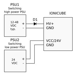
Two switching power supplies, one high power voltage supply for motor and one low power supply for logic circuity. A diode D1 is normally necessary to protect regenerative current flow going back to PSU1. For recommended diodes, see paragraph below. |
- Fault tolerant
- Availability of parts
- Any motor supply voltage possible
|
- Switching PSUs typically don't allow temporary overloading
|
 |
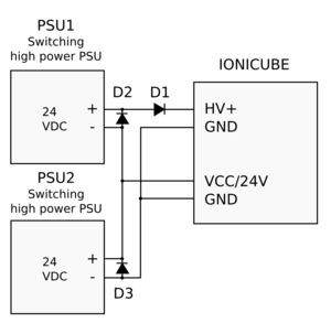
Two similar high power supplies are used to supply both motor and logic voltages. In this system power of PSU1 and PSU2 will contribute to motor supply, i.e. if both supplies are rated 200W, then total power available to drives is ~400W. Diodes D1 is normally needed to protect power supplies from regenerative power and D2/D3 to protect power supplies in the case where one power supply would shut down (i.e. on overload). For recommended diodes, see the paragraph below. |
- Cost saving (i.e. 2x200W 24V cost less than a 1x400W 48V)
- Availability of parts
|
- In case of PSU2 fault/overload, drive 24V logic supply voltage may be instabilized (erratic drive behavior, or resetting drive)
- Switching PSUs typically don't allow temporary overloading
|
 |
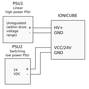
Linear (transformer based unregulated) power supply is used for motor supply and low power switching PSU for logic power. |
- No need for diodes
- Linear PSU peak power handling
- Any motor supply voltage possible
|
- Size & weight
- Lower availability of linear power supplies
- Fluctuation of AC mains voltage may trigger overvoltage fault on drives if PSU voltage is normally near drive's maximum
|
 |
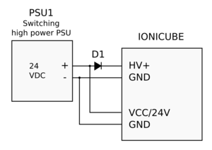
Single PSU (max 24V) is feeding logic and motor.
Note: IONICUBEs logic supply can be fed anything between 9 to 24V, however some functionality (mech brake output, VFD output) may not work properly below 24V. If these features are not needed, then also lower voltage can be used.
|
- Low cost
- Availability of parts
- Compact
|
- Limited voltage
- In case of PSU fault/overload, drive 24V logic supply voltage may be instabilized (erratic drive behavior, or resetting drive)
|
Diodes D1-D3 are typical silicon or schottky rectifier diodes that are sufficiently rated to carry the present voltages and currents. As diodes are inexpensive, there is no need to avoid oversizing them. Examples diodes:
- Diodes Inc. 10A02-T (10A 100V, leaded)
- Diodes Inc. 10A04-T (10A 400V, leaded)
- Fairchild FFPF30UP20STU (30A, 200V, leaded, isolated TO-220 case)
- Fairchild RURG3060 (30A 600V, leaded, non-isolated case - cooling tab is either anode or cathode)
- Fairchild STPS20120D (20A 120V, leaded, non-isolated case - cooling tab is either anode or cathode)
| Some switching power supplies can tolerate reversed current flow from drive to PSU (renegerative current). In case of such PSU, D1 may be omitted. If unsure about PSU behavior in regeneration, always add D1. |
| Leaded diodes may be easiest to install right at PSU terminals, no extra wiring needed. |


