File list
This special page shows all uploaded files.
First page |
Previous page |
Next page |
Last page |
| Date | Name | Thumbnail | Size | User | Description | Versions |
|---|---|---|---|---|---|---|
| 21:13, 13 February 2013 | IntensifyEfficiency.png (file) |  |
28 KB | Tero K | Intensify Nx50 efficiency vs load current | 1 |
| 19:38, 13 February 2013 | Idc10pin connector.pdf (file) | 205 KB | Tero K | Typical 10 pin IDC ribbon cable connector spec sheet | 1 | |
| 01:01, 5 January 2013 | Multidrop addressing.png (file) |  |
53 KB | Tero K | 1 | |
| 00:32, 5 January 2013 | Dipswitch.png (file) | 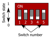 |
38 KB | Tero K | 3 | |
| 22:22, 20 December 2012 | Info.png (file) |  |
104 KB | Tero K | 1 | |
| 21:38, 17 December 2012 | Dangermachine.gif (file) |  |
5 KB | Tero K | 1 | |
| 21:31, 17 December 2012 | Dangerelectric.gif (file) |  |
4 KB | Tero K | electric shock hazard | 1 |
| 21:30, 17 December 2012 | Dangerexplosive.gif (file) |  |
6 KB | Tero K | 1 | |
| 21:29, 17 December 2012 | Dangertemperature.gif (file) |  |
4 KB | Tero K | 1 | |
| 21:21, 17 December 2012 | Explosive.png (file) |  |
33 KB | Tero K | 1 | |
| 17:14, 17 December 2012 | Brakingreswiring.png (file) |  |
36 KB | Tero K | 1 | |
| 17:13, 17 December 2012 | Brakingreswiring.svg (file) |  |
9 KB | Tero K | 2 | |
| 12:18, 17 December 2012 | Electricshock.png (file) |  |
39 KB | Tero K | 1 | |
| 11:56, 17 December 2012 | Regenres.jpg (file) | 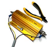 |
903 KB | Tero K | 250 Watt regenerative resistor | 1 |
| 13:23, 15 December 2012 | J1closeup.png (file) |  |
48 KB | Tero K | Argon J1 connector | 1 |
| 21:11, 13 December 2012 | Multidrop estop.svg (file) |  |
13 KB | Tero K | 2 | |
| 20:48, 13 December 2012 | RJ-45 TIA-568A Left.png (file) |  |
24 KB | WikiAdmin | 1 | |
| 20:59, 10 September 2012 | VMC100 KU v101 page1.gif (file) | 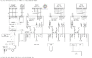 |
68 KB | Koneistaja | VMC100 schematic v1.01 page 1 | 1 |
| 21:32, 14 June 2012 | VSDtestInput2.png (file) | 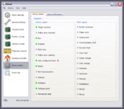 |
104 KB | WikiAdmin | 1 | |
| 21:31, 14 June 2012 | VSDtestInput1.png (file) | 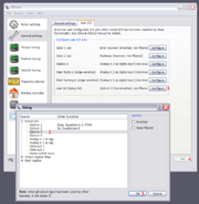 |
123 KB | WikiAdmin | 1 | |
| 17:52, 16 May 2012 | VSDE grounding scheme.png (file) | 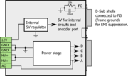 |
54 KB | WikiAdmin | 1 | |
| 17:51, 16 May 2012 | VSDE Grounding scheme.svg (file) | 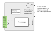 |
45 KB | WikiAdmin | 2 | |
| 22:53, 14 May 2012 | Vsdebob.jpg (file) | 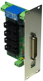 |
39 KB | Tero K | VSDEPI board | 1 |
| 22:50, 14 May 2012 | Vsdepi v1.1 schematics.pdf (file) | 587 KB | Tero K | VSDEPI schematics | 1 | |
| 21:40, 3 May 2012 | CartesianRobot.gif (file) |  |
12 KB | WikiAdmin | From http://www.robotmatrix.org/images/CartesianRobotWorkSpace.gif | 1 |
| 10:24, 2 May 2012 | StepperMotor.jpg (file) |  |
8 KB | WikiAdmin | Typical stepping motor with frame size of 1.7x1.7 inches. File from http://opensourceecology.org/wiki/File:StepperMotor.jpg | 1 |
| 19:04, 19 April 2012 | Jv2xy.jpg (file) | 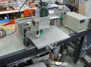 |
151 KB | Tero K | 1 | |
| 12:20, 19 April 2012 | Cascade position controller.png (file) |  |
82 KB | Tero K | 1 | |
| 22:32, 18 April 2012 | Ferritebead.jpg (file) | 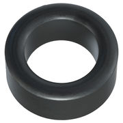 |
154 KB | WikiAdmin | 1 | |
| 22:32, 18 April 2012 | Ferrirebeads.jpg (file) | 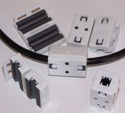 |
49 KB | WikiAdmin | 1 | |
| 21:01, 18 April 2012 | Force-torque-wrench.jpg (file) | 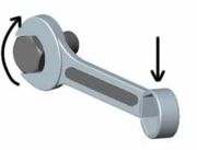 |
3 KB | WikiAdmin | 1 | |
| 21:01, 18 April 2012 | Turning.jpg (file) |  |
28 KB | WikiAdmin | Image from Sandvik | 1 |
| 21:00, 18 April 2012 | Positioning-Cross-Hairs.jpg (file) |  |
22 KB | WikiAdmin | 1 | |
| 19:57, 18 April 2012 | Smlibtestmain shrink.png (file) |  |
40 KB | WikiAdmin | 1 | |
| 19:49, 18 April 2012 | Dctoolvista.png (file) |  |
52 KB | WikiAdmin | 1 | |
| 17:31, 18 April 2012 | Pwm wiki.png (file) | 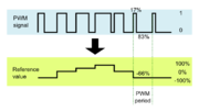 |
25 KB | Tero K | 1 | |
| 17:16, 18 April 2012 | Pulse and direction wiki.png (file) |  |
19 KB | Tero K | 1 | |
| 17:15, 18 April 2012 | Pulse and direction wiki.svg (file) |  |
12 KB | Tero K | 4 | |
| 12:28, 18 April 2012 | Servomotor and feedback.png (file) | 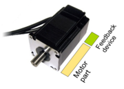 |
75 KB | Tero K | 1 | |
| 23:00, 17 April 2012 | VSD-A.jpg (file) |  |
51 KB | WikiAdmin | VSD-A drives | 1 |
| 22:35, 17 April 2012 | Gdtool25.png (file) | 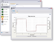 |
86 KB | WikiAdmin | GDtool 2.5 with plots | 1 |
| 23:13, 12 April 2012 | Deadtime schematics freescale.png (file) | 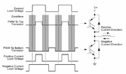 |
39 KB | Tero K | Description of the image: Schematic: typical single phase half-bridge PWM power output consisting two transistors and an inductive load (inductor). In 3 phase motor drives there are 3 pcs of this kind of circuits excluding inductor (which is replaced | 1 |
| 22:25, 12 April 2012 | Torqueripple w deadtime distortion.png (file) |  |
50 KB | Tero K | Actual motor torque ripple caused by dead time distortion and motor is rotating (thus current direction changes every now and then as seen in dips). In ideal case the graph should be flat (constant torque). | 1 |
| 22:24, 12 April 2012 | Currentripple w deadtime correction2.png (file) | 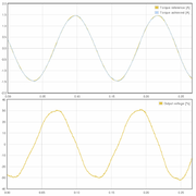 |
59 KB | Tero K | Sinusoidal current distortion reduced when distortion correction applied. | 1 |
| 22:23, 12 April 2012 | Currentripple w deadtime distortion.png (file) | 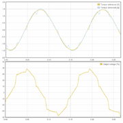 |
60 KB | Tero K | Sinusoidal current distortion caused by dead time distortion without any distortion correction applied. | 1 |
| 16:05, 30 March 2012 | Quadrature Diagram.svg (file) |  |
18 KB | WikiAdmin | Quadrature signals | 1 |
| 22:36, 29 March 2012 | Ticketsystem.png (file) |  |
46 KB | Tero K | 1 | |
| 23:57, 26 March 2012 | Uncheckedwiki.png (file) |  |
1 KB | WikiAdmin | Unchecked symbol in wiki | 1 |
| 18:36, 26 March 2012 | VSD-EXE.jpg (file) |  |
127 KB | Tero K | Reverted to version as of 18:03, 26 March 2012 | 4 |
| 18:11, 26 March 2012 | VSD-EXE-160-w430.jpg (file) |  |
62 KB | Tero K | VSD-E and VSD-XE 160V models | 1 |
First page |
Previous page |
Next page |
Last page |