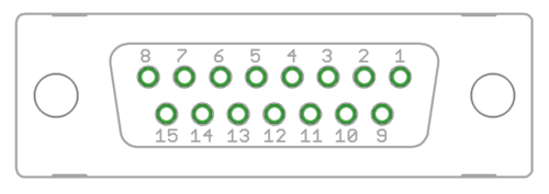
Template:EncoderPinoutD15
From Granite Devices Knowledge Wiki
| Pin # | Pin name | Electrical type (in most feedback device modes) | Quadrature encoder | SinCos encoder | BiSS-C encoder | SSI encoder | AMS SSI encoder |
|---|---|---|---|---|---|---|---|
| Shell | GND | Earth/case | |||||
| 1 | HALL_W | Hall sensor digital input, phase W | - | - | - | ||
| 2 | HALL_V | Hall sensor digital input, phase V | - | - | - | ||
| 3 | HALL_U | Hall sensor digital input, phase U | - | - | - | ||
| 4 | GND | Encoder supply ground | |||||
| 5 | B- | Differential input B- | Channel B- | SinCos input B- | - | - | - |
| 6 | B+ | Differential input B+ | Channel B+ | SinCos input B+ | - | - | - |
| 7 | A- | Differential input A- | Channel A- | SinCos input A- | - | - | - |
| 8 | A+ | Differential input A+ | Channel A+ | SinCos input A+ | - | - | - |
| 9 | 5V_OUT | Encoder supply 5V output | |||||
| 10 | GND | Encoder supply ground | |||||
| 11 | GPI3 | Axis negative direction end limit switch (optional). Normally closed (NC) switch is highly recommended for safety reasons. Connect it between this pin and GND pin. Normally open (NO) switch can be used, and the switch polarity can be changed in Granity/Fault limits tab. |
Clock/MA- | Clock- | CLK | ||
| 12 | GPI2 | Axis positive direction end limit switch (optional).Normally closed (NC) switch is highly recommended for safety reasons. Connect it between this pin and GND pin. Normally open (NO) switch can be used, and the switch polarity can be changed in Granity/Fault limits tab. |
Clock/MA+ | Clock+ | CSn | ||
| 13 | GPI1 | Axis home switch switch (optional). Normally closed (NC) switch is highly recommended for safety reasons. Connect it between this pin and GND pin. Normally open (NO) switch can be used, and the switch polarity can be changed in Granity/Goals tab in Homing section. |
DO | ||||
| 14 | C- | Differential input C- | Index channel Z- | Index channel Z+ | Data/SLO- | Data- | - |
| 15 | C+ | Differential input C+ | Index channel Z+ | Index channel Z+ | Data/SLO+ | Data+ | - |
| Pin layout | Female D-sub 15 connector as it appears from outside of drive. Note: counterpart (male) connector has mirrored pin layout if viewed from pin side, and same layout if viewed from soldering side. | ||||||
