Servo tuning basics
Driving a servo motor is much like driving a car. Driving a car has many similarities including the key concepts of torque, velocity and position control. Most of this happens in the driver's head the same way than a servo drive does with a motor.
Driving (a.k.a servoing) a car
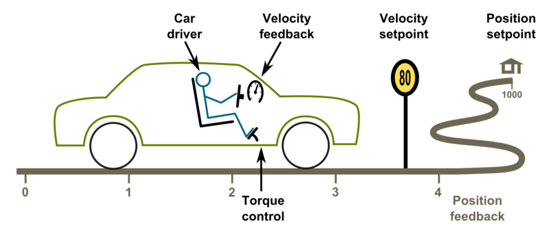
Driving a car to a destination is much like driving a servo motor to it's destination position. The analogies in between are:
| Car | Servo axis |
|---|---|
| Pedal (motor gasoline feed) | Torque setpoint (motor current feed) |
| Speed limit | Velocity setpoint |
| Target location | Position setpoint |
| Speed meter | Velocity feedback |
| Trip meter | Position feedback |
| Car driver | Servo drive |
The ultimate goal of driver is to get to the target. To achieve this, he follows the road (trajectory) at certain velocity and decelerates once target is being reached. Without knowing, the driver acts as servo controller where he:
- Controls car's velocity based on the speed meter value and speed limit
- Controls car's position based on trip meter's reading or by observing location trough the windshield
- All actions the driver makes, is based on comparing the setpoints and the actual state
Driver as a controller
What is a controller gain and a PI controller
Controller gain means sensitivity to change output due to tracking error (the difference between setpoint and feedback).
The simplest form of feedback based controller is a proportional gain controller (P controller) where output follows the formula output = Pgain*(setpoint-feedback). The problem of proportional gain controller is that it may never reach the setpoint because output starts approaching zero when the following error is reaching zero.
Because of this, it's better to add in integrating component to the controller (forming PI controller). Integrator accumulates the tracking error to a integrator variable. Integrator variable is like a bucket of water, when you add water, the water level rises and when you take out water, the level lowers. In controller the equation becomes: output = Pgain*(setpoint-feedback) + Igain*IntegralOf(setpoint-feedback).
The characteristics of feedback gain variables:
- P-gain - reacts instantly to the tracking error but can't eliminate tracking error completely
- I-gain - reacts slowly over time, adjusts output until tracking error is zero
When driving a car, human brain closely resembles the operation of a PI controller. For in-depth info about PI controllers and its variants, see the Wikipedia article PID controller.
Tuning the gains
Controller tuning means finding of the optimum gain values for the given system.
The proper gain values always depend on many aspects, especially the target system dynamic properties (such as motor properties, axis transmission ratios, inertias and masses). Change of properties introduces the requirement of tuning the gain values as gain values that work fine in one system may not behave satisfactory on a different system.
In servo drive case, this means that each motor type and mechanical axis need to be tuned separately. However, if axis and motors are identical, then the same gains should work equally.
Gain tuning (car) example
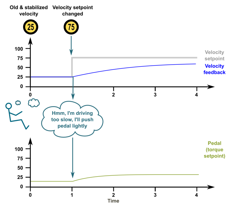
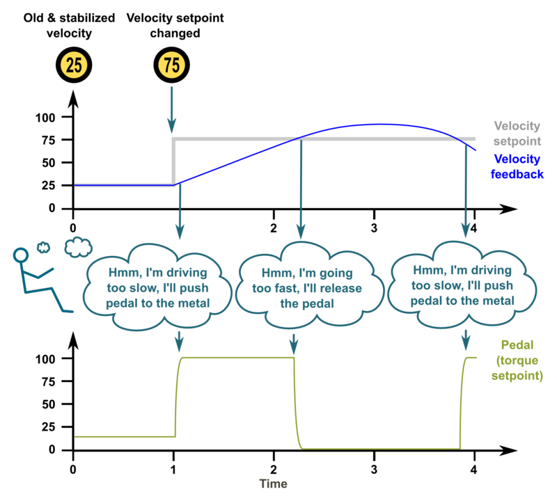
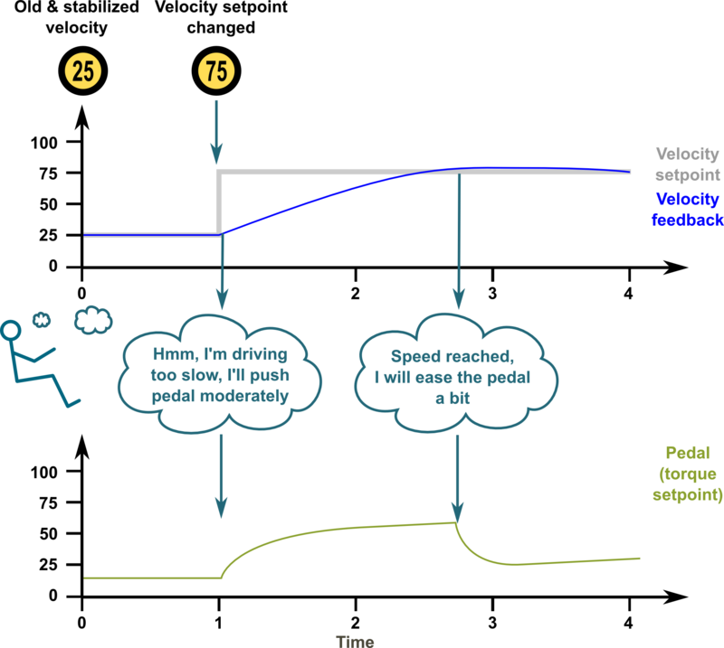
The following series of images illustrate an imaginary car driving scenario where the driver acts as velocity controller of the car. The magnitude of PI gain values equal the driver's aggressivity of controlling the pedal to reach the desired speed.
Low gains - sluggish response
If the gains are set too low, the system response tends to be sluggish and sometimes leave a static tracking error (not reaching setpoint in any time). In this imaginary case we could think PI gains to be P=20 I=10.
Too high gains - oscillation & instability
If the gains are set too high, the system becomes overshooting, oscillating and less stable. Here the comparable PI gains could be P=200 I=100
Optimum gains - only little overshoot
When the gains are tuned correctly, the response shows rapid response with low overshoot and no ringing or oscillations. The comparable gains here P=50 I=25.
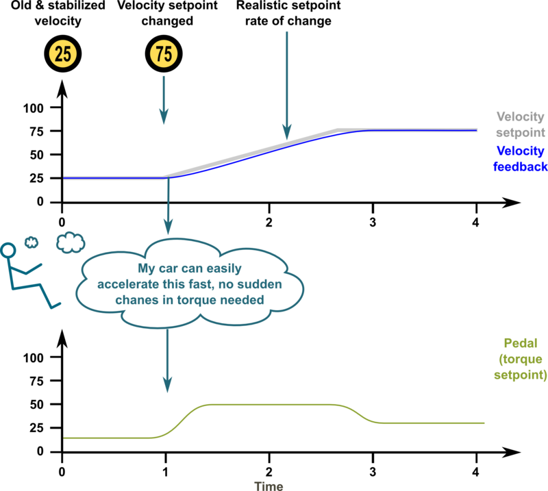
Optimum gains with realistic setpoint - optimum response
The response can be improved further by introducing a limit to the slew rate of setpoint signal. The controller behaves optimally when the system is able to follow the setpoint continuously with little tracking error. In this case the gains could be same as before, P=50 I=25.
In no event the Product Information or parts hereof shall be regarded as guarantee of conditions or characteristics. The Product Information or any part thereof may also not be regarded as a warranty of any kind. No liability of any kind shall be assumed by Author with respect to Product Information or any use made by you thereof, nor shall Author indemnify you against or be liable for any third party claims with respect to such information or any use thereof.
As content of this Wiki may be edited by user community, Granite Devices Oy or it's affiliates do not take any responsibility of the contents of this Wiki. Use information at your own risk. However, Granite Devices staff attempts to review all changes made to this Wiki and keep information trustworthy.
Without written consent, Granite Devices' Products or Intellectual Property shall not be used in situations or installations where living beings, material property, or immaterial property could be harmed by the operation, features or failures of Product. Products may only be used in a way where hazards like moving parts, electric shock, laser radiation, or fire can't be realized even if the content of this Wiki would suggest otherwise.
