File:Deadtime schematics freescale.png
From Granite Devices Knowledge Wiki
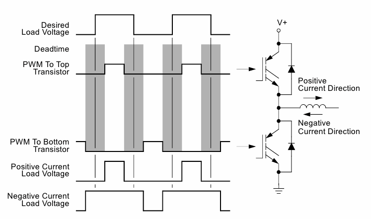
Revision as of 23:13, 12 April 2012 by Tero K (Talk | contribs) (Description of the image: Schematic: typical single phase half-bridge PWM power output consisting two transistors and an inductive load (inductor). In 3 phase motor drives there are 3 pcs of this kind of circuits excluding inductor (which is replaced)
Deadtime_schematics_freescale.png (747 × 441 pixels, file size: 39 KB, MIME type: image/png)
Description of the image:
   Schematic: typical single phase half-bridge PWM power output consisting two transistors and an inductive load (inductor). In 3 phase motor drives there are 3 pcs of this kind of circuits excluding inductor (which is replaced by a motor coil).
   Desired load voltage waveform: the distortion free waveform reference signal on load that we would want to see.
   PWM to top transistor: PWM signal that is controls when the top side transistor is in conductive state.
   PWM to bottom transistor: PWM signal that is controls when the bottom side transistor is in conductive state.
   Grey areas: time when neither of PWM signals are in "on" state making both transistor non-conductive. This is necessary to prevent on-state overlapping and shoot-through currents from V+ to GND.
   Positive current load voltage: this is the achieved (distorted) PWM signal on load when current direction is positive in load inductor.
   Negative current load voltage: this is the achieved (distorted) PWM signal on load when current direction is negative in load inductor.
As it figure shows, actual output voltage differs from desired load voltage. Actual PWM duty cycle either becomes higher or lower than desired and distortion direction changes whenever current direction reverses.
Image from Freescale MC56F8300UM.
File history
Click on a date/time to view the file as it appeared at that time.
| Date/Time | Thumbnail | Dimensions | User | Comment | |
|---|---|---|---|---|---|
| current | 23:13, 12 April 2012 |  | 747 × 441 (39 KB) | Tero K (Talk | contribs) | Description of the image: Schematic: typical single phase half-bridge PWM power output consisting two transistors and an inductive load (inductor). In 3 phase motor drives there are 3 pcs of this kind of circuits excluding inductor (which is replaced |
- You cannot overwrite this file.
File usage
The following page links to this file:
