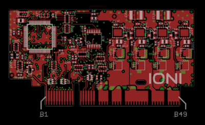
IONI connector pinout
IONI card edge connector fits into a standard PCI-Express 8X socket connector.
Pinout
The pinout of IONI drive is provided in the following table.
- I/O and low voltage signals
| Pin | Signal name | Pin | Signal name | |
|---|---|---|---|---|
| A1 | GND | B1 | 5V_IN | |
| A2 | RS485_A | B2 | RS485_B | |
| A3 | ADDRSEL1 | B3 | ADDRSEL2 | |
| A4 | HSIN1 | B4 | HSIN2 | |
| A5 | ANAIN- | B5 | ANAIN+ | |
| A6 | GPI1 | B6 | GPI2 | |
| A7 | GPI3 | B7 | GPI4 | |
| A8 | GPO1 | B8 | GPO2 | |
| A9 | GPO3 | B9 | GPO4 | |
| A10 | GPO5 | B10 | GPO6 | |
| A11 | REGEN_OUT | B11 | MECH_BRAKE_OUT | |
| A12 | ENABLE_IN | B12 | Reserved/NC | |
| A13 | STO2 | B13 | HALL_W | |
| A14 | HALL_V | B14 | HALL_U | |
| A15 | CHA- | B15 | CHA+ | |
| A16 | CHB- | B16 | CHB- | |
| A17 | CHC- | B17 | CHC- |
- Power signals
| Pin | Signal name | Pin | Signal name | |
|---|---|---|---|---|
| A18-A22 | GND | B18 | Not connected | |
| A23 | Not connected | B19-B22 | HV+ | |
| A24-A27 | PHASE1 | B23 | Not connected | |
| A28 | Not connected | B24-B27 | PHASE2 | |
| A29-A37 | PHASE3 | B28 | Not connected | |
| A38 | Not connected | B29-B37 | PHASE4 | |
| A39-A43 | PHASE1 | B38 | Not connected | |
| A44 | Not connected | B39-B43 | PHASE2 | |
| A45-A49 | GND | B44 | Not connected | |
| B45-B49 | HV+ |
Note: pins marked as Not connected are left empty for to make larger clearance for high voltage signals. Leave these pins unconnected on motherboard designs.
Electrical ratings
| Signal names | Allowed input voltages/output voltage | Internal input/output impedance (Ω) | Internal pull impedance (Ω) |
|---|---|---|---|
| 5V_IN | 5V +/-10% | - | - |
| HV+ | 0 – 55 V | - | - |
| RS485_A/B | RS485 serial bus, 2.7-5.5V signal level | >10k | - |
| ADDRSEL1, ADDRSEL2 | Pulldown resistors to ground, minimum 2.2 kOhm. See article Setting IONI bus address. | - | 2.2k pull-up |
| HSIN1, HSIN2 | Logic low -0.3-1.0V, logic high 2.7-5.5V | - | 2.2k pull-up |
| ANAIN-, ANAIN+ | +/- 11V | 8k | - |
| GPI1...GPI4 | Logic low -0.3-1.0V, logic high 2.7-5.5V | - | 2.2k pull-up |
| GPO1...GPO6 | Logic low 0V, logic high 3.3V | 220 | - |
| MECH_BRAKE_OUT | Logic low 0V, logic high 3.3V | 220 | - |
| REGEN_OUT | Logic low 0V, logic high 3.3V | 220 | - |
| ENABLE_IN | Logic low -0.3-1.0V, logic high 2.7-26V | 5k | 10k pull-down |
| STO2 | Logic low -0.3-2.0V, logic high 4.5-26V | 8k | 20k pull-down |
| HALL_U/V/W | Logic low -0.3-1.0V, logic high 2.7-5.5V | - | 2.2k |
| CHA/B/C+ | RS422 receiver, 2.7-5.5V signal level | - | 2.2k |
| CHA/B/C- | RS422 receiver, 2.7-5.5V signal level | - | 1.1k pull to 2.5V |
In no event the Product Information or parts hereof shall be regarded as guarantee of conditions or characteristics. The Product Information or any part thereof may also not be regarded as a warranty of any kind. No liability of any kind shall be assumed by Author with respect to Product Information or any use made by you thereof, nor shall Author indemnify you against or be liable for any third party claims with respect to such information or any use thereof.
As content of this Wiki may be edited by user community, Granite Devices Oy or it's affiliates do not take any responsibility of the contents of this Wiki. Use information at your own risk. However, Granite Devices staff attempts to review all changes made to this Wiki and keep information trustworthy.
Without written consent, Granite Devices' Products or Intellectual Property shall not be used in situations or installations where living beings, material property, or immaterial property could be harmed by the operation, features or failures of Product. Products may only be used in a way where hazards like moving parts, electric shock, laser radiation, or fire can't be realized even if the content of this Wiki would suggest otherwise.
