Assembling SimuCUBE 480W/720W kit
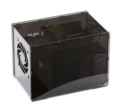
This guide gives instructions of assembling a Granite Devices SimuCUBE kit for 480W/720W power supply options. The kit of needed parts is available through Granite Devices web shop and also has been offered through SimuCUBE indiegogo campaign.
Contents
Tools and parts needed
Tools
- Metric hex keys (2.5 + 3 + 4 mm)
- Suitable wrench or pliers to hold M3 and M4 nuts
- Small file, might be needed to touch off some of the laser cut tenons to ease up the assembly and prevent the use of excessive force
- Suitable crimpers for wire terminals or a soldering iron
Parts (included in the full kit)
- SimuCUBE + IONI drive
- 7 acrylic pieces for the case
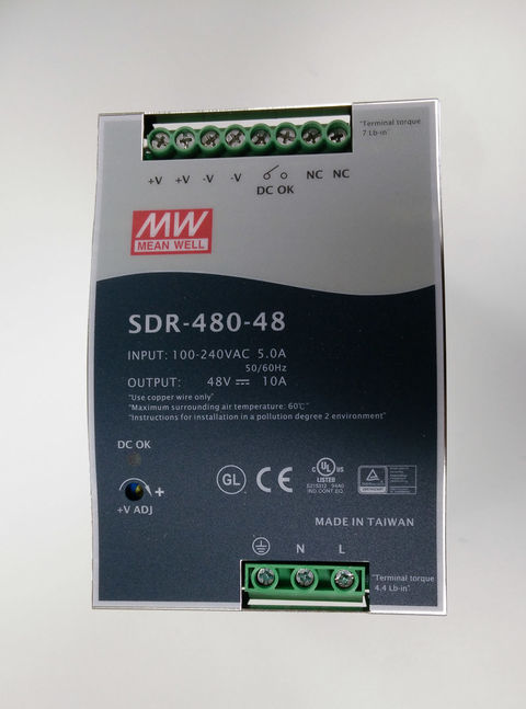
- Meanwell NDR-480 or SDR-480 power supply
- 4x M3x6 button head screw
- 6x M3x10 button head screw
- 2x M3x10 countersunk screw
- 4x M4x16 socket screw
- 4x M5x10 button head screw
- 2x M3 locking nut
- 4x M4 locking nut
- 2x threaded 10mm brass cubes
- Schurter DC11.00001.003 IEC power socket (Farnell 1207680
- 80x80x25mm cooling fan capable of starting at 5V
- 1.5 mm^2 wire for electrical connections
- 1.5 mm^2 yellow-green wire for grounding
Optional
- Gloves to prevent fingerprints on the acrylic parts while assembling the system
- Wire end ferrules
- Heat shrink tubing
Assembly
| Assembly requires wiring of mains voltages that can be lethal. Consult an electrician if you are unsure of your skills. Everything published here is provided as-is without any warranty, you do everything on your on responsibility and Granite Devices Inc. cannot be held responsible if you harm yourself, others or burn your house down because of miswiring. |
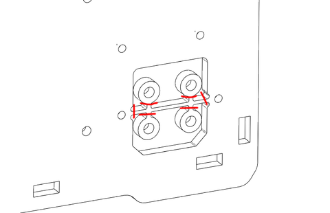
1) Cut off the round parts from the acrylic back plate and save these for later. These will be used as spacers for the SimuCUBE motherboard.
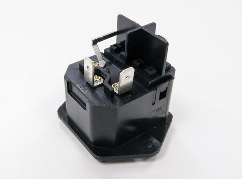
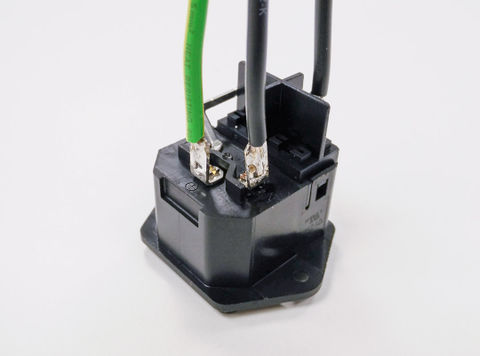
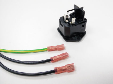
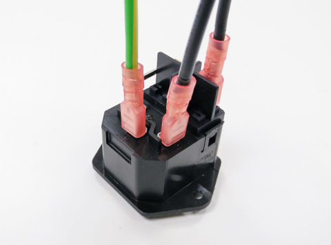
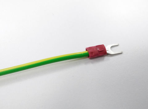
2) Attach grounding and mains wires to the power connector by either soldering them or by using the crimp terminals. If you don't have an access to proper crimp pliers for these type of terminals, then soldering is more preferred method to prevent wires from getting loose.
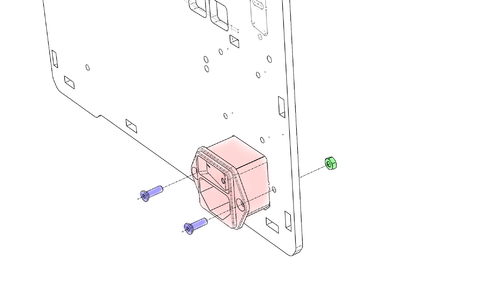
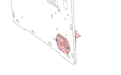
3) Fix the power plug to the acrylic back plate with M3x10 countersunk screws and M3 locking nuts.
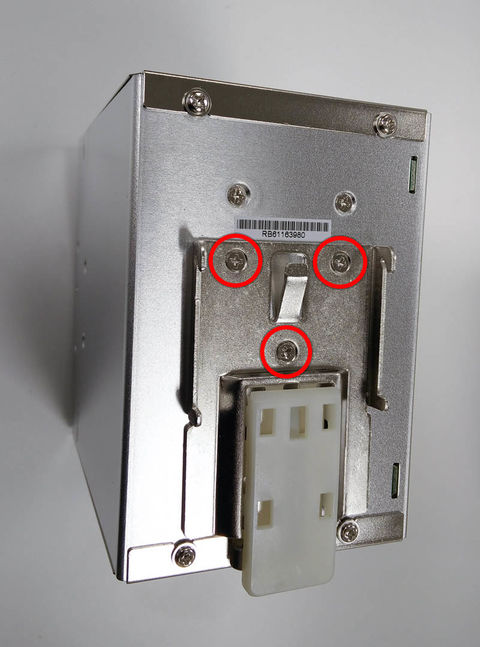
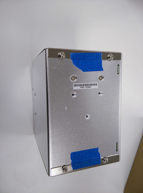
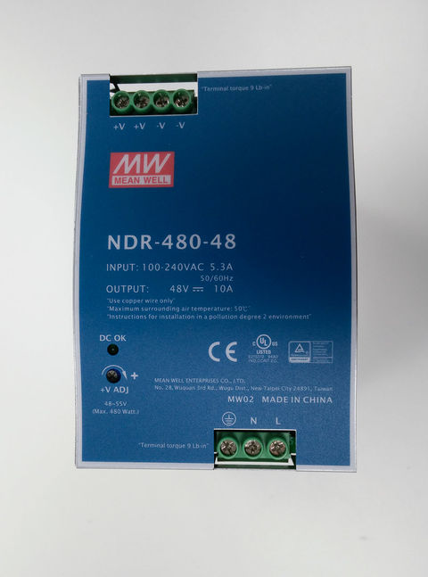
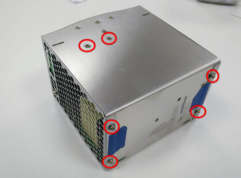
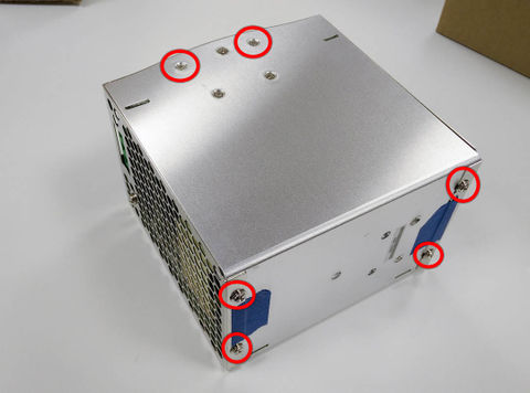
4) Put the two pieces of thin tape to the power supply as in the image (helps with assembly). Unscrew the marked screws to detach the DIN rail connector and the other marked screws. Follow the instructions with the type of power supply you have (SDR-480 or NDR-480).
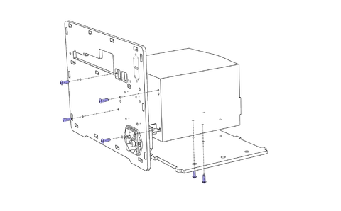
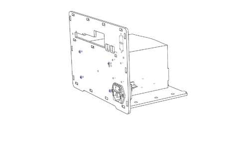
5) Attach the power supply to the back plate with four M3x10 button head screws (be careful, do not tighten too much!). Slide the bottom plate below the power supply (use the two screwless holes on the bottom of the PSU as a reference to align the bottom) and to the slots on the back plate and screw two M3x10 button head screws from the bottom.
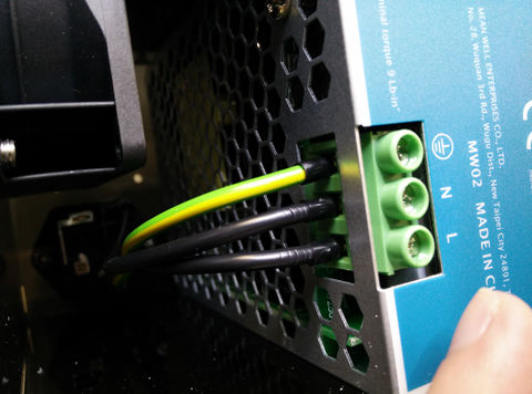
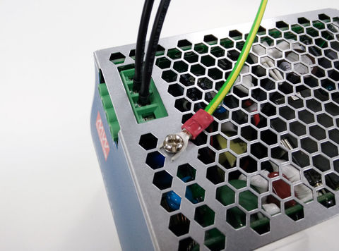
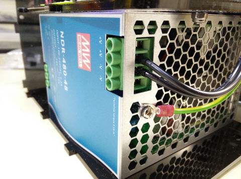
6) Connect grounding and mains wires to the power supply's screw terminal.
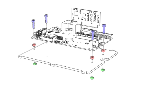
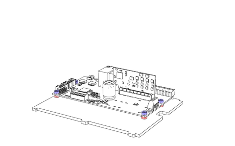
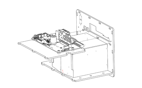
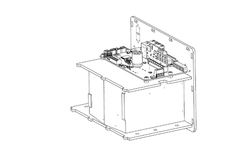
7) Attach IONI to the SimuCUBE motherboard by pressing it to the PCI-E-type connector. Align the motherboard onto the acrylic middle piece so that the edge of the connector edge of the circuit board is flush with the main edge of the acrylic (not the three protruding parts) and the holes line up. Use the four spacers cut from the acrylic back plate, four M4x16 screws and four locking nuts.
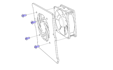
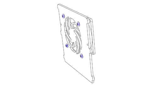
8) Attach the 80mm fan on the acrylic side piece with four M5x10 button head screws, use the photo as a reference on which way the fan should be aligned. This configuration sucks air to the case and blows it towards the IONI and through the power supply.
9) Slide the motherboard assembly on top of the power supply and into the slots on the back of the case.
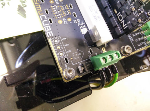
10) Attach positive (+48VDC), negative and grounding wires between the power supply output and motherboard terminals. Crimp the fork terminal on the other end of the grounding cable and do a pull test to make sure it is crimped well.
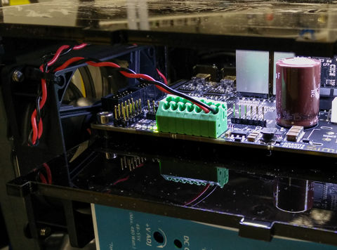
11) Attach the fan side plate in place and attach the fan wires to the quick terminal on the motherboard.
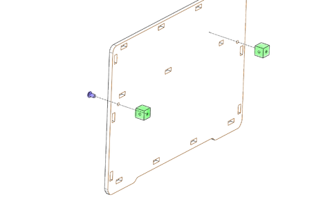
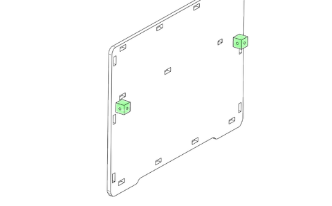
12) Attach the two 10mm threaded cubes to the acrylic front plate with M3x6 button head screws and align the holes as shown on the image.
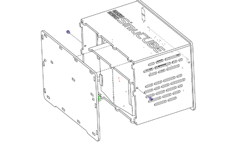
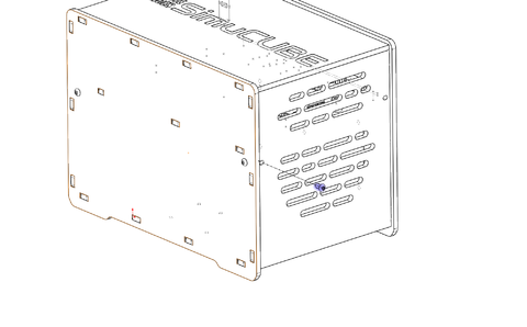
13) Attach the left exhaust panel and top panel with the logo to the case and carefully wiggle the front plate in place. Screw one M3x6 button head screw from either side to the 10mm threaded cubes previously attached to the front plate.
14) Follow the SimuCUBE system user guide for usage
Read next
|
In no event the Product Information or parts hereof shall be regarded as guarantee of conditions or characteristics. The Product Information or any part thereof may also not be regarded as a warranty of any kind. No liability of any kind shall be assumed by Author with respect to Product Information or any use made by you thereof, nor shall Author indemnify you against or be liable for any third party claims with respect to such information or any use thereof.
As content of this Wiki may be edited by user community, Granite Devices Oy or it's affiliates do not take any responsibility of the contents of this Wiki. Use information at your own risk. However, Granite Devices staff attempts to review all changes made to this Wiki and keep information trustworthy.
Without written consent, Granite Devices' Products or Intellectual Property shall not be used in situations or installations where living beings, material property, or immaterial property could be harmed by the operation, features or failures of Product. Products may only be used in a way where hazards like moving parts, electric shock, laser radiation, or fire can't be realized even if the content of this Wiki would suggest otherwise.
