Difference between revisions of "Control modes"
| [checked revision] | [checked revision] |
| Line 32: | Line 32: | ||
[[Category:Setup guides]] | [[Category:Setup guides]] | ||
==Controller structure== | ==Controller structure== | ||
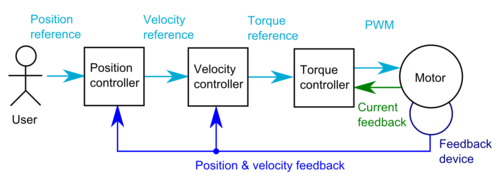
| − | [[File:Cascade position controller.png|thumb|500px|VSD drive block diagram in position mode.]] | + | [[File:Cascade position controller.png|thumb|500px|VSD drive block diagram in position mode. Limiters are not pictured. ]] |
| − | VSD drives use cascaded controllers. So for example in velocity mode torque controller and velocity contoller are connected in series so that torque reference is generated by velocity controller. Position mode is same as velocity controller except the velocity reference is generated by position controller. | + | VSD drives use cascaded controllers. So for example in velocity mode, torque controller and velocity contoller are connected in series so that torque reference is generated by velocity controller. Position mode is same as velocity controller except the velocity reference is generated by position controller. |
Cascaded structure leads to more flexible features and enables higher dymamic performance compared to direct PWM or torque control from position controller. | Cascaded structure leads to more flexible features and enables higher dymamic performance compared to direct PWM or torque control from position controller. | ||
| + | |||
| + | ;Torque controller stucture | ||
| + | :User torque rererence → Torque limiter → Torque controller outputs motor PWM | ||
| + | ;Velocity controller stucture | ||
| + | :User velocity reference → Velocity limiter → Velocity controller outputs torque rererence → Torque limiter → Torque controller outputs motor PWM | ||
| + | ;Position controller stucture | ||
| + | :User position reference → Position controller outputs velocity reference → Velocity limiter → Velocity controller outputs torque rererence → Torque limiter → Torque controller outputs motor PWM | ||
| + | |||
| + | Limiters simply cut and saturate reference signal if user specified torque/velocity limit is exceeded. | ||
Revision as of 12:42, 19 April 2012
There are three main control modes in motion & motor control are torque, velocity and position control.
Torque control
Torque control mode makes motor a torque or force transducer. I.e. user sets torque reference to 1 Nm, then motor will produce 1 Nm torque regardless of spinning speed. In torque mode user can not set limits to velocity or position.
- Typical applications
- Racing/flight simulators
- Feeding/pulling
- Cascaded controller after velocity or position controller
- Non-motion applications: high current LED & Peltier driver when drive used just as adjustable current source
Velocity control
Goal of velocity control is to regulate motor speed. I.e. if user velocity reference is 500 rpm, then motor attempts to rotate exactly at 500 rpm no matter how much load is attached to motor. In velocity mode user can set limits for torque but not for position.
- Typical applications
- Screw tightening robot when used with torque limit
- Spindles
- Feeding
- Fans & pumps
- Position control when used with external or internal position controller
Position control
Position control mode attempts to provide precision positioning. Motor follows reference set point and if set point is kept constant, motor holds position even if external forces attempt to displace it. In position mode user can set limits to torque and velocity.
- Typical applications
- CNC
- Pick & place machines
- 2D/3D printing
- Robotics
Controller structure
VSD drives use cascaded controllers. So for example in velocity mode, torque controller and velocity contoller are connected in series so that torque reference is generated by velocity controller. Position mode is same as velocity controller except the velocity reference is generated by position controller.
Cascaded structure leads to more flexible features and enables higher dymamic performance compared to direct PWM or torque control from position controller.
- Torque controller stucture
- User torque rererence → Torque limiter → Torque controller outputs motor PWM
- Velocity controller stucture
- User velocity reference → Velocity limiter → Velocity controller outputs torque rererence → Torque limiter → Torque controller outputs motor PWM
- Position controller stucture
- User position reference → Position controller outputs velocity reference → Velocity limiter → Velocity controller outputs torque rererence → Torque limiter → Torque controller outputs motor PWM
Limiters simply cut and saturate reference signal if user specified torque/velocity limit is exceeded.


