Difference between revisions of "Pulse burst positioning"
From Granite Devices Knowledge Wiki
| [checked revision] | [checked revision] |
(→Doing incremental move) |
(→Monitoring when motion is complete) |
||
| Line 63: | Line 63: | ||
/*motion is not complete, wait some time and poll again*/ | /*motion is not complete, wait some time and poll again*/ | ||
| − | Delay_ms(0.01 | + | Delay_ms(10); /* 0.01 seconds */ |
waited=waited+0.01; | waited=waited+0.01; | ||
} | } | ||
Revision as of 13:24, 12 December 2013

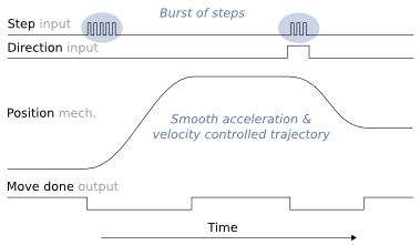
Illustration of input step pulse & direction signals, motor position and move done output as function of time.
Pulse burst positioning is a setpoint method based on pulse and direction signals. In pulse burst mode, controller need only to generate a burst of pulses with direction signal to begin a motion relative to current position. Motion will comply with pre-configured acceleration and velocity limits of the drive.
Contents
Pulse burst positioning properties
- Simplicity - easy to understand and implement point-to-point motion
- No real-time pulse train controller needed - smooth motion profile is generated inside the drive
- Exact - setpoint signal path is fully digital
- Change setpoint on the fly - not necessary to wait for motion to finish before sending new pulses
How to use
Pulse burst is the minimalistic yet high performing position setpoint method available. Suitable signal may be generated by various means:
- PLC
- A simple timer & counter circuit
- Microcontroller GPIO pin
- Or any programmable device with controllable digital outputs
Practical example
Drive parameterization
In Argon the following configuration enables burst pulse mode:
- Set CM as Position control
- Set CRI as Pulse train & direction
- Set CAL and CVL to your desired acceleration and velocity values
- Wire J5 connector according to this diagram
Doing incremental move
The C-style code below generates the signaling.
void IncrementalMove( int distance )
{
  int i;

  /* set direction output pin */
  if(distance<0)
    SetDirectionOutputPin(0);
  else
    SetDirectionOutputPin(1);

  /* generate step pulses to start motion. quantity of pulses = distance */
  for( i=0; i< abs(distance); i++ )
  {
    Delay_ms(0.001);
    SetPulseOutputPin(1);
    Delay_ms(0.001);
    SetPulseOutputPin(0);
  }
}
- SetPulseOutputPin sets the digital state of HSIN1 pin on Argon
- SetDirectionOutputPin sets the digital state of HSIN2 pin on Argon
Monitoring when motion is complete
Returns true when motion has successfully finished. False if timeout expired or drive faulted.
bool WaitForMoveDone( double timeout )
{
  double waited=0;

  while(waited<timeout)
  {
    if( GetMotionCompletePinState() == true )
      return true; /* motion is now complete, return true*/

    if( GetFaultPinState() == true )
      return false; /* drive is in fault state, return false*/

    /*motion is not complete, wait some time and poll again*/
    Delay_ms(10); /* 0.01 seconds */
    waited=waited+0.01;
  }

  /*return false because timeouted */
  return false;
}
- GetMotionCompletePinState reads the GPO1 pin state from Argon
- GetFaultPinState reads the GPO3 pin state from Argon
Usage example
IncrementalMove(500);
WaitForMoveDone();
IncrementalMove(1000);
WaitForMoveDone();
IncrementalMove(-1500);
WaitForMoveDone();