Pulse burst positioning

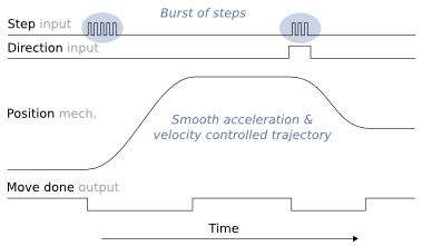
Pulse burst positioning means a setpoint signaling based on pulse and direction format. In burst mode, controller need only to generate a burst of pulses with direction signal to drive to begin a motion relative to current position complying with pre-configured acceleration and velocity limits.
- Pulse burst positioning properties
- Simplicity - easy to understand and implement point-to-point motion control
- Exact - setpoint signal path is fully digital
- No real-time controller needed - smooth trajectory is generated inside the drive
Contents
How to use
Pulse burst is the minimalistic yet high performing position setpoint method available. Suitable signal may be generated by various means:
- PLC
- A simple timer & counter circuit
- Microcontroller GPIO pin
- Or any programmable device with controllable digital outputs
Practical example
Drive parameterization
In Argon the following configuration enables burst pulse mode:
- Set CM as Position control
- Set CRI as Pulse train & direction
- Set CAL and CVL to your desired acceleration and velocity values
- Wire J5 connector according to this diagram
Doing incremental move
The C-style code below represents the signaling.
void IncrementalMove( int distance )
{
  int i;

  /* set direction output pin */
  if(distance<0)
    SetDirectionOutputPin(0);
  else
    SetDirectionOutputPin(1);

  /* send step pulses to start motion */
  for( i=0; i< abs(distance); i++ )
  {
    Delay_ms(0.001);
    SetPulseOutputPin(1);
    Delay_ms(0.001);
    SetPulseOutputPin(0);
  }
}
- SetPulseOutputPin sets the digital state of HSIN1 pin on Argon
- SetDirectionOutputPin sets the digital state of HSIN2 pin on Argon
Monitoring when motion is complete
bool WaitForMoveDone( double timeout )
{
  double waited=0;

  while(waited<timeout)
  {
    if( GetMotionCompletePinState() == true )
      return true; /* motion is now complete, return true*/

    /*motion is not complete, wait some time and poll again*/
    Delay_ms(0.01);
    waited=waited+0.01;
  }

  /*return false because timeouted */
  return false;
}
- GetMotionCompletePinState reads the GPO1 pin state from Argon
Usage example
IncrementalMove(500);
WaitForMoveDone();
IncrementalMove(1000);
WaitForMoveDone();
IncrementalMove(-1500);
WaitForMoveDone();
In no event the Product Information or parts hereof shall be regarded as guarantee of conditions or characteristics. The Product Information or any part thereof may also not be regarded as a warranty of any kind. No liability of any kind shall be assumed by Author with respect to Product Information or any use made by you thereof, nor shall Author indemnify you against or be liable for any third party claims with respect to such information or any use thereof.
As content of this Wiki may be edited by user community, Granite Devices Oy or it's affiliates do not take any responsibility of the contents of this Wiki. Use information at your own risk. However, Granite Devices staff attempts to review all changes made to this Wiki and keep information trustworthy.
Without written consent, Granite Devices' Products or Intellectual Property shall not be used in situations or installations where living beings, material property, or immaterial property could be harmed by the operation, features or failures of Product. Products may only be used in a way where hazards like moving parts, electric shock, laser radiation, or fire can't be realized even if the content of this Wiki would suggest otherwise.