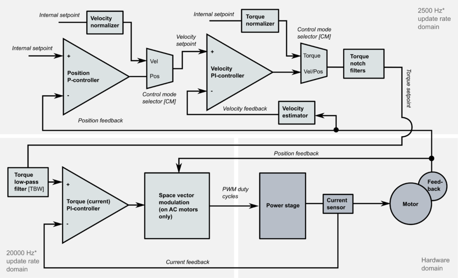
Signal path of motor drive
In Granite Devices drives the torque, velocity and position limits and setpoints are defined as integer numbers. The vales are represented "hardware" scale which are described below.
Setpoint signal path[edit | edit source]
Setpoint signal path converts user setpoint to internal setpoint.
Setpoint signal path[edit | edit source]
Main parts are:
- Input multiplier. Purpose of this is to increase resolution of input setpoint to allow more fine grained velocity & acceleration control in trajectory planner. By default Setpoint multiplierMUL value is 50.
- Setpoint smoothing filter. If enabled, applies low pass filter to signal reducing jitter and roughness of signal but also introduces about some delay. By default the filter has 100% attenuation at 250Hz.
- Trajectory planner. This limits rate of change of setpoint signal based on Velocity limitCVL and Acceleration limitCAL parameters. Output rate maximum rate of change:
- Velocity changes max Acceleration limitCAL nubmer of units per control cycle (control cycle is 400µs in most GD drives)
- Velocity maximum value is limited to Velocity limitCVL
- Input divider. This divides setpoint signal by Setpoint dividerDIV to give desired output scale for internal setpoint. Combination of multiplier and divider can be used change total scaling of setpoint signal.
Setpoint source scales[edit | edit source]
Different setpoint sources have different range and scale:
| Setpoint source | Type | Range | Scale |
|---|---|---|---|
| Pulse & directon | Incremental | Infinite |
|
| Quadrature | Incremental | Infinite |
|
| PWM | Absolute | Full input scale equals setpoint range of +/-16384. In loss of PWM signal, setpoint is 0. |
|
| Analog | Full input scale equals setpoint range of +/-16384 | ||
| Serial (SimpleMotion V2) | Absolute & incremental | Infinite |
It should be noted that trajectory planner operates after multiplier meaning that Velocity limitCVL velocity limit value is not in equal scale with velocity setpoint value.
Internal setpoint[edit | edit source]
Internal setpoint is a predefined setpoint scale inside the drive. The scale of internal setpoint signals are:
- Position mode: position sensor counter raw value
- Velocity mode: internal goes through Velocity normalized that changes scales depending on setpoint source:
- In PWM & Analog source: Internal setpoint of +/-16384 represents whole speed range covered by Velocity limitCVL parameter. I.e. 10V input to analog input runs motor at 100% speed and -5V at -50% etc.
- In all other sources: number of feedback device counts per one control cycle. Obtained by calculating the difference of position feedback values at every control cycle.
- Torque mode: Torque normalizer scales internal setpoint so that value of +/-16384 represents full torque scale (i.e. internal setpoint value 16384 outputs configured peak current Peak current limitMMC and 8192 outputs Peak current limitMMC/2)
Controller[edit | edit source]
The default controller type of GD drives is cascaded type where each controlled variable has it's own PI or P controller. In position mode such structure is called as PIV controller.
The block diagram below represents simplified structure of GD drives.
*) Update rates may be drive model specific. 2500 Hz and 20 kHz apply for most drives including IONI and ATOMI. However, torque control domain on ARGON is 17500 Hz.
Calculation formulas and examples[edit | edit source]
These examples focus on calculating values on a rotary motor and linear axis.
Constants used later in calculations[edit | edit source]
Assuming control cycle to be 400µs / 2500 Hz (default in GD drives):
$ f=2500 $
Calculation of how many counts the feedback device produces per one physical unit:
$ X_{FeedbackDeviceCountsPerUnit}=4\frac{P_{FBR}}{P_{AXS}} $
AXS is a number that tells how many physical lenght units (such as millimeters a linear axis) translates per one rotary motor revolution.
Example 1 - Calculating setpoint in position mode[edit | edit source]
Here we convert physical units (such as millimeters) to setpoint value in position control mode:
$ setpoint=\frac{P_{MUL}}{P_{DIV}}*D_{DesiredPosition}*X_{FeedbackDeviceCountsPerUnit} $
Example 2 - Calculating value for CVL parameter[edit | edit source]
Here we convert speed (such as mm/sec, or whatever lenght units AXS represents) to Velocity limitCVL value:
$ P_{CVL}=\frac{V_{DesiredSpeedLimit}*X_{FeedbackDeviceCountsPerUnit}*P_{DIV}}{f} $
Example 3 - Calculating value for CAL parameter[edit | edit source]
Here we convert speed (such as mm/sec2, or whatever lenght units AXS represents) to Acceleration limitCAL value:
$ P_{CAL}=\frac{A_{DesiredAccelerationLimit}*X_{FeedbackDeviceCountsPerUnit}*P_{DIV}}{f^2} $
In alternative method we don't need acceleration value, but just time $ t $ in seconds to define how long motor should take to accelerate from zero speed to maximum speed defined by CAL:
$ P_{CAL}=\frac{P_{CVL}}{tf} $
| Granity calculates real world units thus it can be used to calculate and experiment with the scales. As scales are linear, interpolation of values is viable choice. |
See also[edit | edit source]
In no event the Product Information or parts hereof shall be regarded as guarantee of conditions or characteristics. The Product Information or any part thereof may also not be regarded as a warranty of any kind. No liability of any kind shall be assumed by Author with respect to Product Information or any use made by you thereof, nor shall Author indemnify you against or be liable for any third party claims with respect to such information or any use thereof.
As content of this Wiki may be edited by user community, Granite Devices Oy or it's affiliates do not take any responsibility of the contents of this Wiki. Use information at your own risk. However, Granite Devices staff attempts to review all changes made to this Wiki and keep information trustworthy.
Without written consent, Granite Devices' Products or Intellectual Property shall not be used in situations or installations where living beings, material property, or immaterial property could be harmed by the operation, features or failures of Product. Products may only be used in a way where hazards like moving parts, electric shock, laser radiation, or fire can't be realized even if the content of this Wiki would suggest otherwise.

