Simucube Wireless Wheel 2
| Wireless Wheel 2 Module | |
|---|---|
 | |
 | |
| Configurable inputs | |
| Digital | 96 |
| Analog | 4 |
| Antenna | |
| Type | External (not included) |
| Connector | U.FL |
| Frequency (Center/Band) | 2.4 GHz |
| Gain (max) | 2.14 dBi |
| Electrical specifications | |
| Rechargeable version: | |
| Charger input voltage/current | 5.0V / 450mA |
| Supported battery chemistry | Li-Ion or Li-Po |
| Battery voltage | 2.5V – 4.2V |
| Non-rechargeable version: | |
| Input voltage |
2.0V – 3.8V |
The Simucube Wireless Wheel 2 Module is an upgraded version of the Simucube Wireless wheel module. New module offers more digital inputs, 4 analog axis, in-build battery charger and voltage regulator.
Contents
Digital inputs
Wireless Wheel 2 Module has a total of 98 digital input pins in which 96 inputs are fully configurable by wheel manufacturers. 2 pins are reserved for shifter paddles. Shifter paddles are only mandatory devices, and the rest of the pins can be used as needed. Paddles are mandatory, since those are used to connect and disconnect wheel from Simucube. Each configurable IO pin can be used multiple times with different device types. Most of the input devices can also be configured with enable pins. These enable pins can be used to multiplex encoders. For example, one encoder can be configured as 12 different encoders with rotary switch controlling which encoder is used at time.
Possible digital input device types:
Button: Regular button, game controller holds signal high if button is pressed.
Encoder: Each detent from encoder is shown as pulse from game controller. Pulsed game controller signal depends on turning direction.
Rotary switch: Maximum of 12 positions. Changing switch position will pulse corresponding output. Rotary switch can also be configured as buttons, if pulsing output is not needed or wanted.
Analog inputs
Wireless module offers AVCC output for analog devices. Output in AVCC is pulsed for lower power consumption and output is on only when the ADC module is sampling inputs. Output pulses are 2ms long and frequency is 100Hz, this means that AVCC is on 20% of the time. 2ms pulses work great with potentiometers, but Hall-effect sensors might not work with pulsed AVCC if Hall-sensor power-on time is too long. One option to provide VCC for Hall-sensor is to power it from Wireless Wheel 2 VDD pin and use MOSFETs connected to SLEEP pin so Hall-sensor can be powered off while Wireless Wheel 2 isn’t connected. SLEEP pin is high when Wireless Wheel 2 is connected to Simucube.
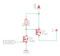
SLEEP pin with transistors can be used to turn external devices on and off

Battery connections
Wireless Wheel 2 Module has multiple VIN, GND, BATT and SW_IN pin. Module will work with only one of each used, but it is recommended to connect pins together in wheel circuit board. Pins should be tied together to ensure reliable connection with M.2 connector is case of mechanical shock or shaking.
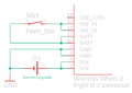
Rechargeable version
Wireless Wheel 2 Module for rechargeable batteries has in-built charger circuit and DC-DC converter to regulate battery voltage to 3.0V. Charger is connected to VIN and should be provided with 5.0V +- 5% with minimum of 450mA for charging. BATT pins are charger output and battery should be connected between these and GND. SW_IN is unregulated voltage input for Wireless Wheel 2 Module and will provide voltage to in-built DC-DC converter. Power switch can be connected between SW_IN pins and positive battery terminal. installing power switch between SW_IN and BATT enable charging when wheel is turned off.
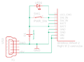
Non-rechargeable version
Wireless Wheel 2 Module version for non-rechargeable batteries does not have charger nor DC-DC converter. Due to non-existing DC-DC converter, modules VDD output is not regulated, and voltage will be same as battery voltage. Even though it is possible to connect batteries straight to SW_IN pins to power this version, it is recommended to connect battery positive lead to VIN instead, since it has reverse polarity protection. VIN is internally connected to BATT pins in non-rechargeable version. If power switch is needed, it can be installed to battery leads or between BATT and SW_IN pins. If power switch is not connected between mentioned pins, BATT pins should be connected to WS_IN pins to ensure power for module.
Rechargeable example
Non-rechargeable example


Pinout
Wireless Wheel 2 Module uses M.2 connectors to fit all the I/O pins in a compact, low-profile packet. All LED pins include a 220 Ohm current limiter resistor.
Left M.2 connector
| Bottom side | Top side | ||||
|---|---|---|---|---|---|
| Function | Signal | Pin | Signal | Function | |
| GND | GND | 66 | 67 | AVCC | 3.0 V OUTPUT to analog circuitry Max. 100 mA including VDD current. |
| GND | GND | 64 | 65 | AN0 | ADC CH0 INPUT 0 .. 3.0 V voltage range |
| GND | GND | 62 | 63 | AN1 | ADC CH1 INPUT 0 .. 3.0 V voltage range |
| GND | GND | 60 | 61 | AN2 | ADC CH2 INPUT 0 .. 3.0 V voltage range |
| Input | BTN64 | 58 | 59 | AN3 | ADC CH3 INPUT 0 .. 3.0 V voltage range |
| Input | BTN63 | 56 | 57 | BTN1 | Input |
| Input | BTN62 | 54 | 55 | BTN2 | Input |
| Input | BTN61 | 52 | 53 | BTN3 | Input |
| Input | BTN60 | 50 | 51 | BTN4 | Input |
| Input | BTN89 | 48 | 49 | BTN5 | Input |
| Input | BTN58 | 46 | 47 | BTN6 | Input |
| Input | BTN57 | 44 | 45 | BTN7 | Input |
| Input | BTN56 | 42 | 43 | BTN8 | Input |
| Input | BTN55 | 40 | 41 | BTN9 | Input |
| Input | BTN54 | 38 | 39 | BTN10 | Input |
| Input | BTN53 | 36 | 37 | BTN11 | Input |
| Input | BTN52 | 34 | 35 | BTN12 | Input |
| Input | BTN51 | 32 | 33 | BTN13 | Input |
| Input | BTN50 | 30 | 31 | BTN14 | Input |
| Input | BTN49 | 28 | 29 | BTN15 | Input |
| GND | GND | 26 | 27 | BTN16 | Input |
| Input | BTN80 | 24 | 25 | GND | GND |
| Input | BTN78 | 22 | 23 | BTN79 | Input |
| Input | BTN76 | 20 | 21 | BTN77 | Input |
| Input | BTN74 | 18 | 19 | BTN75 | Input |
| Input | BTN72 | 16 | 17 | BTN73 | Input |
| Input | BTN70 | 14 | 15 | BTN71 | Input |
| Input | BTN68 | 12 | 13 | BTN69 | Input |
| Input | BTN66 | 10 | 11 | BTN67 | Input |
| Input | BTN17 | 8 | 9 | BTN65 | Input |
| Input | BTN19 | 6 | 7 | BTN18 | Input |
| Input | BTN32 | 4 | 5 | LED1 | 3.0 V status LED OUTPUT through 220 Ohm series resistor |
| Input | BTN30 | 2 | 3 | BTN20 | Input |
| - | - | - | 1 | BTN31 | Input |
Right M.2 connector
| Bottom side | Top side | ||||
|---|---|---|---|---|---|
| Function | Signal | Pin | Signal | Function | |
| Input | BTN28 | 66 | 67 | BTN29 | Input |
| Input | BTN26 | 64 | 65 | BTN27 | Input |
| Input | BTN22 | 62 | 63 | BTN25 | Input |
| Input | BTN24 | 60 | 61 | BTN21 | Input |
| Do not connect | - | 58 | 59 | BTN23 | Input |
| Do not connect | - | 56 | 57 | - | Do not connect |
| Input | BTN96 | 54 | 55 | - | Do not connect |
| Input | BTN95 | 52 | 53 | - | Do not connect |
| Input | BTN94 | 50 | 51 | - | Do not connect |
| Input | BTN93 | 48 | 49 | - | Do not connect |
| Input | BTN92 | 46 | 47 | SLEEP | BP2 module sleep status Active LOW (BP2 sleeps) |
| Input | BTN91 | 44 | 45 | TX | LEUART TX signal OUTPUT |
| Input | BTN90 | 42 | 43 | RX | LEUART RX signal INPUT |
| Input | BTN89 | 40 | 41 | LED2 | 2nd indicator LED OUTPUT 3.0 V through 220 Ohm resistor |
| Input | BTN88 | 38 | 39 | PADDLE1 | Paddle input 1 (left) |
| Input | BTN87 | 36 | 37 | PADDLE2 | Paddle input 2 (right) |
| Input | BTN86 | 34 | 35 | GND | GND |
| Input | BTN85 | 32 | 33 | VDD | +3.0 V OUTPUT Max. 100 mA including AVCC current. |
| Input | BTN84 | 30 | 31 | BTN33 | Input |
| Input | BTN83 | 28 | 29 | BTN34 | Input |
| Input | BTN82 | 26 | 27 | BTN35 | Input |
| Input | BTN81 | 24 | 25 | BTN36 | Input |
| GND | GND | 22 | 23 | BTN37 | Input |
| GND | GND | 20 | 21 | BTN38 | Input |
| LED indicator for battery charging Connect LED Anode to BATT |
LED_CHG | 18 | 19 | BTN39 | Input |
| SWITCH_IN operating voltage input | SW_IN | 16 | 17 | BTN40 | Input |
| SW_IN | 14 | 15 | BTN41 | Input | |
| LiPO/Ion/battery positive terminal | BATT | 12 | 13 | BTN42 | Input |
| BATT | 10 | 11 | BTN43 | Input | |
| GND | GND | 8 | 9 | BTN44 | Input |
| GND | 6 | 7 | BTN45 | Input | |
| Voltage INPUT terminal 5.0 V ± 5 % |
VIN | 4 | 5 | BTN46 | Input |
| VIN | 2 | 3 | BTN47 | Input | |
| - | - | - | 1 | BTN48 | Input |
Resources
Eagle library
Eagle library of Wireless Wheel 2 Module
3D-model
Wireless Wheel 2 Module 3D model file (.step)
In no event the Product Information or parts hereof shall be regarded as guarantee of conditions or characteristics. The Product Information or any part thereof may also not be regarded as a warranty of any kind. No liability of any kind shall be assumed by Author with respect to Product Information or any use made by you thereof, nor shall Author indemnify you against or be liable for any third party claims with respect to such information or any use thereof.
As content of this Wiki may be edited by user community, Granite Devices Oy or it's affiliates do not take any responsibility of the contents of this Wiki. Use information at your own risk. However, Granite Devices staff attempts to review all changes made to this Wiki and keep information trustworthy.
Without written consent, Granite Devices' Products or Intellectual Property shall not be used in situations or installations where living beings, material property, or immaterial property could be harmed by the operation, features or failures of Product. Products may only be used in a way where hazards like moving parts, electric shock, laser radiation, or fire can't be realized even if the content of this Wiki would suggest otherwise.