Difference between revisions of "Using drive with PLC"
| [checked revision] | [checked revision] |
(Created page with "Typical step & direction connection scheme with PLC Granite Devices drives are compatible with virtually all PLC syste...") |
(Tag: VisualEditor) |
||
| Line 5: | Line 5: | ||
In pulse & direction mode, PLC sends stream of pulses with direction signal to modify motor position incrementally. This is the de-facto standard for driving stepping motors. However with Granite Devices drives, any motor type can be operated with step & direction interface. | In pulse & direction mode, PLC sends stream of pulses with direction signal to modify motor position incrementally. This is the de-facto standard for driving stepping motors. However with Granite Devices drives, any motor type can be operated with step & direction interface. | ||
| − | *Choose PLC with pulse & direction (a.k.a. step & direction or stepper interface). Output level 5V single ended or RS422. | + | *Choose PLC with pulse & direction (a.k.a. step & direction or stepper interface). Output level 5V single ended or RS422. As an example, see [https://www.beckhoff.com/english.asp?ethercat/el2522.htm EL2522] from Beckhoff that is compatible interface device. |
*Use PLC's general purpose inputs & outputs (GPIO) to control and read status signals of drive, such as: | *Use PLC's general purpose inputs & outputs (GPIO) to control and read status signals of drive, such as: | ||
**Drive enable (output) | **Drive enable (output) | ||
Revision as of 16:28, 14 December 2017
Granite Devices drives are compatible with virtually all PLC systems through several connection methods.
Contents
Connection types
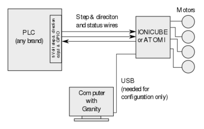
Pulse & direction with motion control PLC
In pulse & direction mode, PLC sends stream of pulses with direction signal to modify motor position incrementally. This is the de-facto standard for driving stepping motors. However with Granite Devices drives, any motor type can be operated with step & direction interface.
- Choose PLC with pulse & direction (a.k.a. step & direction or stepper interface). Output level 5V single ended or RS422. As an example, see EL2522 from Beckhoff that is compatible interface device.
- Use PLC's general purpose inputs & outputs (GPIO) to control and read status signals of drive, such as:
- Drive enable (output)
- Fault clear (output)
- Drive fault status (input)
- PLC should have motion control functionality inside for trajectory generation
Pulse & direction without motion control PLC
This is similar to traditional step & direction, but can be implemented 100% by PLC software and with just 5V GPIO terminals.
Controlling position smoothly over software generated step pulses is possible thanks to pulse burst positioning (read this page for usage) support in Granite Devices drives.
PLC requirements then are:
- 5 Volt GPIO lines. Typically used:
- drive enable (output)
- fault clear (output)
- drive fault status (input)
- step (output)
- direction (output)
SimpleMotion
If PLC has programmable RS485 serial interface, with 460800 PBS baudrate support, it is possible to convert SimpleMotion library to PLC and control drives with reduced amount of wires and with increased set of functionality.
Drawback of this method is the extra work of porting SimpleMotion C library to PLC. If you implement SimpleMotion for PLC, and wish get good karma by contributing your work to the community, please contact us.
