Difference between revisions of "Configuring linear servo motor"
| [checked revision] | [checked revision] |
| Line 25: | Line 25: | ||
*Set [[FBR]] Feedback device resolution to a value calculated as: Lines per mm*Pole pair pitch. | *Set [[FBR]] Feedback device resolution to a value calculated as: Lines per mm*Pole pair pitch. | ||
| − | For example if we have a linear encoder with 100 pulses per mm and a linear motor with 50 mm pole pair pitch (25 mm pole pitch), we calculate FBR=100*50 = 5000. | + | For example if we have a linear encoder with 100 pulses per mm and a linear motor with 50 mm pole pair pitch (25 mm pole pitch), we calculate FBR = 100*50 = 5000. If the FBR value becomes larger than 50000, then a special drive firmware may be necessary (request it from Granite Devices). |
| + | |||
| + | Set [[MTC]] Thermal time constant according to your motor. If the value is unknown, it is recommended to start with low values such as 30 seconds as the forcer of linear motor may have very low time constant. MTC attempts to protect motor from overheating. | ||
Finally as usual, [[FBI]] parameter must be set properly to achieve proper configuration. | Finally as usual, [[FBI]] parameter must be set properly to achieve proper configuration. | ||
Revision as of 21:13, 27 September 2013
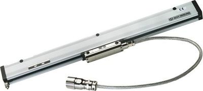
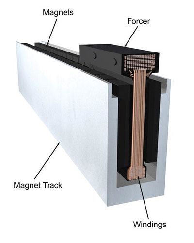
Linear servo motor is an actuator producing linear force or motion and is constructed from a linear motor and a linear feedback device such as linear encoder.
Linear servo motor is electrically equivalent to a rotary motor, so drive sees no difference between the two. However, as drive parameters are entered for rotary motor only, they need some calculations to suit for linear motor.
Configuration
Preparations
Needed parameters of linear motor:
- Magnetic pole pitch (or pole pair pitch)
- Forcer winding specifications:
- Maximum currents: continuous and peak
- Inductance and resistance
- Thermal time constant (optional but recommended)
Needed linear feedback device parameters:
- Resolution (lines or pulses per millimeter)
Conversion of parameters
In this step we convert the values so that motor can be driven from a servo drive. The drive is made to believe that the linear motor is rotary motor, so we need to figure out the equivalent rotary motor parameters.
This example works with Granity software. Follow your drive's setup guide for all parts except these:
- Set MT Motor type as 3 phase AC or BLDC motor
- Set MPC Pole count to 2
- Set FBR Feedback device resolution to a value calculated as: Lines per mm*Pole pair pitch.
For example if we have a linear encoder with 100 pulses per mm and a linear motor with 50 mm pole pair pitch (25 mm pole pitch), we calculate FBR = 100*50 = 5000. If the FBR value becomes larger than 50000, then a special drive firmware may be necessary (request it from Granite Devices).
Set MTC Thermal time constant according to your motor. If the value is unknown, it is recommended to start with low values such as 30 seconds as the forcer of linear motor may have very low time constant. MTC attempts to protect motor from overheating.
Finally as usual, FBI parameter must be set properly to achieve proper configuration.

