Difference between revisions of "SMV2BRK"
From Granite Devices Knowledge Wiki
| [checked revision] | [checked revision] |
| Line 3: | Line 3: | ||
*Terminate the RS485 bus (be the last device on the bus with proper termination impedance) | *Terminate the RS485 bus (be the last device on the bus with proper termination impedance) | ||
*Break out the enable and [[STO]] signals for easy wiring through wire terminals | *Break out the enable and [[STO]] signals for easy wiring through wire terminals | ||
| − | == | + | Before using SMV2BRK, be sure to understand [[SimpleMotion V2 port]]. |
| + | ==Properties== | ||
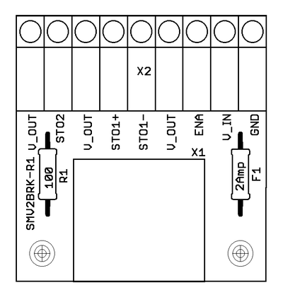
[[File:SMV2BRKbw.png|thumb|Dimensions and pin-out of SMV2BRK]] | [[File:SMV2BRKbw.png|thumb|Dimensions and pin-out of SMV2BRK]] | ||
| + | {| class="wikitable" | ||
| + | |- | ||
| + | ! Pin !! Name !! Function | ||
| + | |- | ||
| + | | 1|| GND|| Ground for 24V power supply. Will be same tied with ground of drive logic supply voltage and [[SimpleMotion V2 USB adapter]] (PC ground). | ||
| + | |- | ||
| + | | 2|| V_IN|| 24VDC supply to SMV2BRK. Use same 24V supply that is used to feed drive 24V logic voltage. | ||
| + | |- | ||
| + | | 3|| ENA|| Enable signal input. Drives disabled when open circuit or pulled to GND, enabled when connected to 24VDC. | ||
| + | |- | ||
| + | | 4 || V_OUT|| 24V output, connected to V_IN through on-board fuse. Used to feed voltage to switches. | ||
| + | |- | ||
| + | | 5|| STO1-|| [[STO]] number 1 negative input. When STO in inactive (motor able to produce toreque), tie GND to this pin. To activate STO1, leave STO1-, STO1+ or both floating. | ||
| + | |- | ||
| + | | 6|| STO1+|| STO number 1 positive input. When STO in inactive (motor able to produce toreque), tie V_OUT to this pin. To activate STO1, leave STO1-, STO1+ or both floating. | ||
| + | |- | ||
| + | | 7|| V_OUT|| 24V output, connected to V_IN through on-board fuse. Used to feed voltage to switches. | ||
| + | |- | ||
| + | | 8|| STO2|| STO number 2 input. STO2 is referenced to GND and to inactivate STO2, connect V_OUT to STO2. To activate STO2, leave floating. | ||
| + | |- | ||
| + | | 9|| V_OUT|| 24V output, connected to V_IN through on-board fuse. Used to feed voltage to switches. | ||
| + | |} | ||
| + | ==Usage== | ||
SMV2BRK is intented to be wired to E-stop button of the motion control system. The following diagram illustrates the preferred wiring: | SMV2BRK is intented to be wired to E-stop button of the motion control system. The following diagram illustrates the preferred wiring: | ||
| − | |||
{{picturebox|Smv2brk Usageschem.png|450px}} | {{picturebox|Smv2brk Usageschem.png|450px}} | ||
| − | |||
For testing purposes, or if no STO or Enable need to be controlled, SMV2BRK may be wired by short pieces of wire which always keep STO disabled and Enable active: | For testing purposes, or if no STO or Enable need to be controlled, SMV2BRK may be wired by short pieces of wire which always keep STO disabled and Enable active: | ||
| − | |||
{{picturebox|Smv2brk Usageschemsimple.png|260px}} | {{picturebox|Smv2brk Usageschemsimple.png|260px}} | ||
==Availability== | ==Availability== | ||
SMV2BRK is available through [[Granite Devices web shop]]. | SMV2BRK is available through [[Granite Devices web shop]]. | ||
| + | [[Category:Hardware]] | ||
| + | [[Category:SimpleMotion]] | ||
| + | [[Category:Argon wiring]] | ||
Revision as of 23:40, 30 October 2014
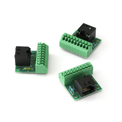
SMV2BRK is a product name for for SimpleMotion V2 break out board. The purpose of SMV2BRK is to:
- Terminate the RS485 bus (be the last device on the bus with proper termination impedance)
- Break out the enable and STO signals for easy wiring through wire terminals
Before using SMV2BRK, be sure to understand SimpleMotion V2 port.
Properties
| Pin | Name | Function |
|---|---|---|
| 1 | GND | Ground for 24V power supply. Will be same tied with ground of drive logic supply voltage and SimpleMotion V2 USB adapter (PC ground). |
| 2 | V_IN | 24VDC supply to SMV2BRK. Use same 24V supply that is used to feed drive 24V logic voltage. |
| 3 | ENA | Enable signal input. Drives disabled when open circuit or pulled to GND, enabled when connected to 24VDC. |
| 4 | V_OUT | 24V output, connected to V_IN through on-board fuse. Used to feed voltage to switches. |
| 5 | STO1- | STO number 1 negative input. When STO in inactive (motor able to produce toreque), tie GND to this pin. To activate STO1, leave STO1-, STO1+ or both floating. |
| 6 | STO1+ | STO number 1 positive input. When STO in inactive (motor able to produce toreque), tie V_OUT to this pin. To activate STO1, leave STO1-, STO1+ or both floating. |
| 7 | V_OUT | 24V output, connected to V_IN through on-board fuse. Used to feed voltage to switches. |
| 8 | STO2 | STO number 2 input. STO2 is referenced to GND and to inactivate STO2, connect V_OUT to STO2. To activate STO2, leave floating. |
| 9 | V_OUT | 24V output, connected to V_IN through on-board fuse. Used to feed voltage to switches. |
Usage
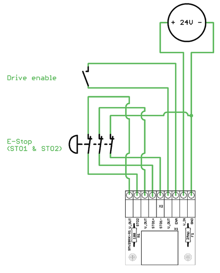
SMV2BRK is intented to be wired to E-stop button of the motion control system. The following diagram illustrates the preferred wiring:
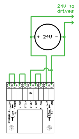
For testing purposes, or if no STO or Enable need to be controlled, SMV2BRK may be wired by short pieces of wire which always keep STO disabled and Enable active:
Availability
SMV2BRK is available through Granite Devices web shop.


