Difference between revisions of "Overvoltage and undervoltage faults"
| [checked revision] | [checked revision] |
(→Overvoltage faults) |
(→Overvoltage faults) |
||
| Line 9: | Line 9: | ||
<gallery widths="330px" heights="500px"> | <gallery widths="330px" heights="500px"> | ||
| − | File:regeneration1.png|Voltage generation during deceleration of motor (motor current is negative, current is pumped to HV DC bus). | + | File:regeneration1.png|Voltage generation during deceleration of motor (motor current is negative, current is pumped to HV DC bus causing a 40 VDC rise). |
| − | File:regeneration2.png|Voltage generation during deceleration of motor (motor current is negative, current is pumped to HV DC bus). However, in this case drive is equipped with regenerative resistor and | + | File:regeneration2.png|Voltage generation during deceleration of motor (motor current is negative, current is pumped to HV DC bus). However, in this case drive is equipped with regenerative resistor and tightly set [[FOV]] parameter which prevents the significant voltage rise (only 5 VDC rise). |
| − | File:regeneration3accel.png|Example of accelerating motor (motor current is positive, power is drawn from HV DC bus which is causing voltage drop). | + | File:regeneration3accel.png|Example of accelerating motor (motor current is positive, power is drawn from HV DC bus which is causing a temporary voltage drop). Rectified 50 Hz mains AC ripple is easily seen in the voltage graph. |
</gallery> | </gallery> | ||
Revision as of 23:11, 23 July 2015
Drive faulting due to voltage fluctuations in HV DC bus are commonly experienced with servo systems. These faults occur when drive measures a HV DC bus supply voltage that is not within the range defined by FUV and FOV parameters. The deviation of voltage may be impossible to notice with multimeter as length of these voltage surges can be in millisecond range.
Contents
Overvoltage faults
Servo drive attached to a motor can act two ways: energy supply and energy consumer. The energy consumer behavior occurs during decelerations and during fast torque reversals, and this causes current flow from motor to drive power supply capacitors. If the generated energy is not absorbed anywhere, the voltage of HV DC bus capacitors will rise above overvoltage threshold (FOV) and trigger an software cleanable overvoltage fault. Overvoltage faults that are caused by returned energy from motor, can be dealt with a regenerative resistor and with optional extra capacitance in HV DC bus.
Scenarios where returned energy is causing the rise of HV DC bus voltage:
- Deceleration of motor speed when there is significant amount of energy stored in mechanical motion (rotating inertia or moving mass). This typically occurs with spindles and linear axes.
- Sudden reversal of torque setpoint. This can generate voltage spike even when motor is standing still. This typically occurs in high bandwidth torque control applications (such as racing simulators). These spikes are very short and an added capacitor to HV DC bus and/or low resistance regenerative resistor might provide a solution.
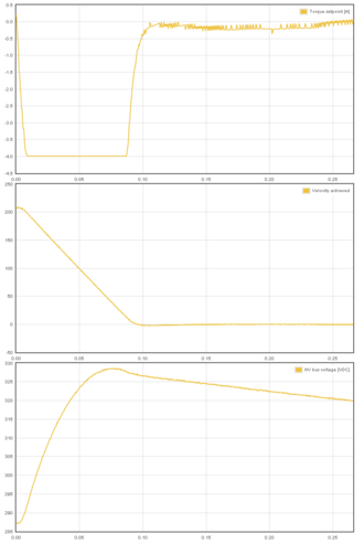
Voltage generation during deceleration of motor (motor current is negative, current is pumped to HV DC bus causing a 40 VDC rise).
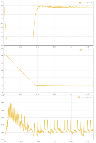
Voltage generation during deceleration of motor (motor current is negative, current is pumped to HV DC bus). However, in this case drive is equipped with regenerative resistor and tightly set FOV parameter which prevents the significant voltage rise (only 5 VDC rise).
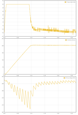
Example of accelerating motor (motor current is positive, power is drawn from HV DC bus which is causing a temporary voltage drop). Rectified 50 Hz mains AC ripple is easily seen in the voltage graph.


Sizing regenerative resistor
The needed regenerative resistor value can be calculated by equation:
$ R_{regen}=\frac{U_{DCBusVoltage}}{I_{PeakMotorCurrent}} $ click to enlarge equations
I.e. if supply voltage is 48VDC and peak current is 10A, then a resistor of 4.8 ohms may be needed to consume all current that is returning from the motor. However, in most practical cases the regenerative current is less than the motor peak current, which allows using higher resistance thus reducing risk of overloading the MOSFET switch operating the resistor. It is recommended to experiment with higher resistor values first, and gradually move to lower resistances if problem persists.
| Before connecting a resistor to drive or drive's motherboard, check from user guides and/or electrical specifications the minimum allowed resistance. Specifications (list may be partial): Argon specifications, IONICUBE electrical specifications, IONICUBE 1X electrical specifications. |
Undervoltage faults
Undervoltages come from drop of power supply voltage during surges. The easiest solution is to set undervoltage paramater [FUV] to a lower value and use power supply that doesn't shut down or drop to near zero under power surges. For very short current surges (millisecond range), an added capacitor to HV DC bus might provide a solution.
Using additional capacitor in HV DC bus
Variables used in equations
- $ t_{duration} $ = time duration in seconds which capacitor should be able to help at maximum current surge
- $ L_{MotorInductance} $ = motor coil inductance in Henrys (use value of ML/1000)
- $ I_{PeakMotorCurrent} $ = motor peak current in Amps (use value of MMC/1000)
- $ U_{MaxVoltageChange} $ = maximum voltage change in HV DC bus during this current surge/peak. I.e. if drive is set to fault at 56V and supply voltage is 48VDC, then 56-48V=8V should be used.
- $ scaler $ = a user chosen value between 0.1 to 1.0. 1.0 is for the worst case where we assume instantaneous torque reversal (rare) and lower values can be used with slower change of torque direction.
| Drive allows voltage few temporarily volts above FOV before faulting. In IONI this voltage is about 4 volts. So when FOV is set to 52V, then drive actually faults at 56V |
Surge duration based method
For short current surges/spikes, a capacitor added to HV DC bus might provide a solution for filtering out the spikes. Capacitor can be sized by equation:
$ C_{filter}=t_{duration}\frac{I_{PeakMotorCurrent}}{U_{MaxVoltageChange}} $ click to enlarge equations
I.e. if current is 20A, surge duration 0.005 seconds and maximum allowed voltage change (increase or drop) during that surge/spike is 10 VDC, then capacitance becomes $ C_{filter}=0.005s\frac{20A}{10V}=0.01F=10000\mu F $.
Motor inductance based method
If the duration is unknown, and we're dealing with fast reversing torque setpoint on a relatively large motor, the capacitor size may be calculated based on the stored energy inside motor inductance:
$ C_{filter}=scaler*L_{MotorInductance}*(\frac{I_{PeakMotorCurrent}}{U_{MaxVoltageChange}})^2 $ click to enlarge equations
I.e. if current is 20A, motor inductance 5 mH (0.005 H) and maximum allowed voltage change in capacitor, and we choose scaler 0.5, then capacitance becomes $ C_{filter}=0.5*0.005H*(\frac{20A}{10V})^2=0.01F=10000\mu F $.
Keeping it practical
Targeting low value in max voltage change will increase capacitor size significantly, and may become unpractical. I.e. if supply voltage is 48V and max voltage is 56V, the max voltage change would be only 8V. Reducing supply voltage by few volts, say 44V, the allowed voltage change becomes 12V which yields much smaller required capacitance (in the above inductance based method example this change would make 2.2 times difference).
| Operating drive near maximum supply voltage limit may cause high requirements for overvoltage prevention. Sometimes it may be easier to reduce supply voltage little bit to make more headroom for voltage increase. Many switching power supplies have a trimpot allowing to adjust voltage up/down by few volts. |