Difference between revisions of "SMV2BRK"
From Granite Devices Knowledge Wiki
| [checked revision] | [checked revision] |
m (Text replacement - "{{param|STO}}" to "STO") |
|||
| (3 intermediate revisions by the same user not shown) | |||
| Line 39: | Line 39: | ||
==Usage== | ==Usage== | ||
| + | {{damage|Pay extra attention to correct wiring in this section. Miswiring or usage of wrong type RJ45 cable (using cross-over cable instead of straight cable) are the most common reasons for damaged drives.}} | ||
SMV2BRK is intended to be wired to E-stop button of the motion control system. The following diagram illustrates the preferred wiring: | SMV2BRK is intended to be wired to E-stop button of the motion control system. The following diagram illustrates the preferred wiring: | ||
{{picturebox|Smv2brk Usageschem.png|450px}} | {{picturebox|Smv2brk Usageschem.png|450px}} | ||
Latest revision as of 20:13, 28 August 2015
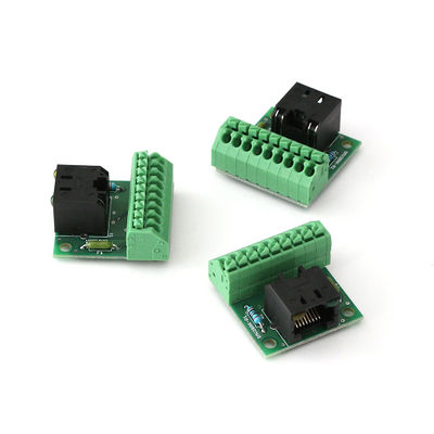
SMV2BRK is a product name for for SimpleMotion V2 break out board. The purpose of SMV2BRK is to:
- Terminate the RS485 bus (be the last device on the bus with proper termination impedance)
- Break out the enable and STO signals for easy wiring through wire terminals
Before using SMV2BRK, be sure to understand SimpleMotion V2 port.
Contents
Functionality[edit | edit source]
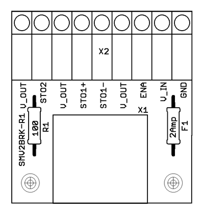
SMV2BRK has two connectors X1 (SimpleMotion V2 RJ45 connector) and X2 (wire terminal for Enable and STO signals).
- STO
- Depending on drive model, they have one or two Safe Torque Off inputs that prevent drive producing any torque to motor if activated. STO has high reliability and is hard-wired to drive power stage making it very reliable aid for machine safety. If drive has two STO inputs, then both STO1 and STO2 must be inactivated simultaneously for drive to operate. STO inputs are designed to be used on emergency stopping situations and not during normal every day drive control.
- Enable
- Every SMV2 compatible drive listens enable signal through SMV bus. Enable signal is a software based enable and useful for non-safety related motor stopping in normal operation.
Pin-out[edit | edit source]
| Pin | Name | Function |
|---|---|---|
| 1 | GND | Ground for 24V power supply. Will be same tied with ground of drive logic supply voltage and SimpleMotion V2 USB adapter (PC ground). |
| 2 | V_IN | 24VDC supply to SMV2BRK. Use same 24V supply that is used to feed drive 24V logic voltage. |
| 3 | ENA | Enable signal input. Drives disabled when open circuit or pulled to GND, enabled when connected to 24VDC. |
| 4 | V_OUT | 24V output, connected to V_IN through on-board fuse. Used to feed voltage to switches. |
| 5 | STO1- | STO number 1 negative input. When STO in inactive (motor able to produce toreque), tie GND to this pin. To activate STO1, leave STO1-, STO1+ or both floating. |
| 6 | STO1+ | STO number 1 positive input. When STO in inactive (motor able to produce toreque), tie V_OUT to this pin. To activate STO1, leave STO1-, STO1+ or both floating. |
| 7 | V_OUT | 24V output, connected to V_IN through on-board fuse. Used to feed voltage to switches. |
| 8 | STO2 | STO number 2 input. STO2 is referenced to GND and to inactivate STO2, connect V_OUT to STO2. To activate STO2, leave floating. |
| 9 | V_OUT | 24V output, connected to V_IN through on-board fuse. Used to feed voltage to switches. |
Usage[edit | edit source]
| Pay extra attention to correct wiring in this section. Miswiring or usage of wrong type RJ45 cable (using cross-over cable instead of straight cable) are the most common reasons for damaged drives. |
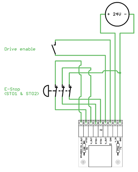
SMV2BRK is intended to be wired to E-stop button of the motion control system. The following diagram illustrates the preferred wiring:
| It is possible to replace Enable switch with transistor driven circuit and E-stop switch with relay. |
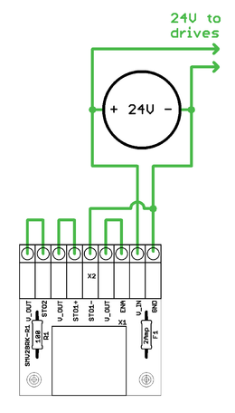
For testing purposes, or if no STO or Enable need to be controlled, SMV2BRK may be wired by short pieces of wire which always keep STO disabled and Enable active:
Availability[edit | edit source]
SMV2BRK is available through Granite Devices web shop.


