Difference between revisions of "Configuring linear servo motor"
| [checked revision] | [checked revision] |
| (3 intermediate revisions by the same user not shown) | |||
| Line 1: | Line 1: | ||
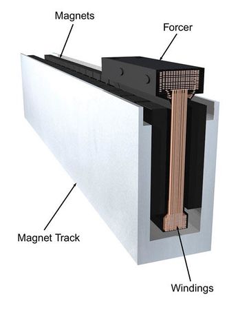
| − | [[File:Linearservo cutaway.jpg|thumbnail|Ironless linear motor cross-section]] | + | [[File:Linearservo cutaway.jpg|thumbnail|Ironless linear motor cross-section|362px]] |
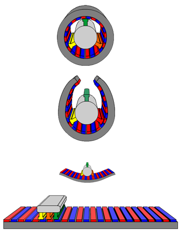
[[File:Linearmotorprinzip.png|thumb|Linear motor works just like rotary synchronous motor that has been cut open and straightened as flat]] | [[File:Linearmotorprinzip.png|thumb|Linear motor works just like rotary synchronous motor that has been cut open and straightened as flat]] | ||
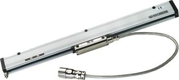
| − | [[File:Linearencoder.jpg|thumbnail|A typical sealed linear encoder]] | + | [[File:Linearencoder.jpg|thumbnail|A typical sealed linear encoder|362px]] |
Linear servo motor is an actuator producing linear force or motion and is constructed from a linear motor and a linear feedback device such as linear encoder. Compared to rotary motor with lead screw, the main benefits of linear servos are very high speeds and zero mechanical backlash. The typical drawbacks are less available force and possibly high design time effort. | Linear servo motor is an actuator producing linear force or motion and is constructed from a linear motor and a linear feedback device such as linear encoder. Compared to rotary motor with lead screw, the main benefits of linear servos are very high speeds and zero mechanical backlash. The typical drawbacks are less available force and possibly high design time effort. | ||
| Line 24: | Line 24: | ||
This example works with [[Granity]] software. Follow your drive's setup guide for all parts except these: | This example works with [[Granity]] software. Follow your drive's setup guide for all parts except these: | ||
| − | #Set | + | #Set {{param|MT}} as 3 phase AC or BLDC motor |
| − | #Set | + | #Set {{param|MPC}} to 2 |
| − | #Set | + | #Set {{param|FBR}} to a value calculated as: Lines per mm*Pole pair pitch. For example if we have a linear encoder with 100 pulses per millimeter and a linear motor with 50 mm pole pair pitch (25 mm pole pitch), we calculate FBR = 100*50 = 5000. '''Important:''' check whether encoder resolution is specified as pulses or cycles per mm OR counts per mm - if it's defined as counts per mm (after 4X decoding), then this value needs to be divided by 4 to get pulses per mm which is the correct input value format. |
| − | #Set | + | #Set {{param|MTC}} according to your motor. If the value is unknown, it is recommended to start with low values such as 30 seconds as the forcer of linear motor may have very low time constant. MTC attempts to protect motor from overheating. |
| − | #Finally as usual, | + | #Finally as usual, {{param|FBI}} parameter must be set properly to achieve proper configuration. |
| − | It's also a good idea to set | + | It's also a good idea to set {{param|AXT}} type to Linear and set {{param|AXS}} to same as pole pair pitch so velocities and distances calculated by Granity will be shown in correct scale. |
{{info|Granity always assumes that we’re setting up a rotary motor, and when choosing linear axis as AXT, it assumes it’s driven by rotary motor (leadscrew/belt/rack'n'pinion transmission). With linear motors, one should imagine words “pole pair” in place of “revolution” in all unit labels in Granity. I.e. when Granity says "mm per revolution" it means "mm per pole pair".}} | {{info|Granity always assumes that we’re setting up a rotary motor, and when choosing linear axis as AXT, it assumes it’s driven by rotary motor (leadscrew/belt/rack'n'pinion transmission). With linear motors, one should imagine words “pole pair” in place of “revolution” in all unit labels in Granity. I.e. when Granity says "mm per revolution" it means "mm per pole pair".}} | ||
Latest revision as of 11:12, 18 June 2016
Linear servo motor is an actuator producing linear force or motion and is constructed from a linear motor and a linear feedback device such as linear encoder. Compared to rotary motor with lead screw, the main benefits of linear servos are very high speeds and zero mechanical backlash. The typical drawbacks are less available force and possibly high design time effort.
Linear servo motor is electrically equivalent to a rotary motor, so drive sees no difference between the two. However, as drive parameters are entered for rotary motor only, they need some calculations to suit for linear motor.
Configuration[edit | edit source]
Preparations[edit | edit source]
Needed parameters of linear motor:
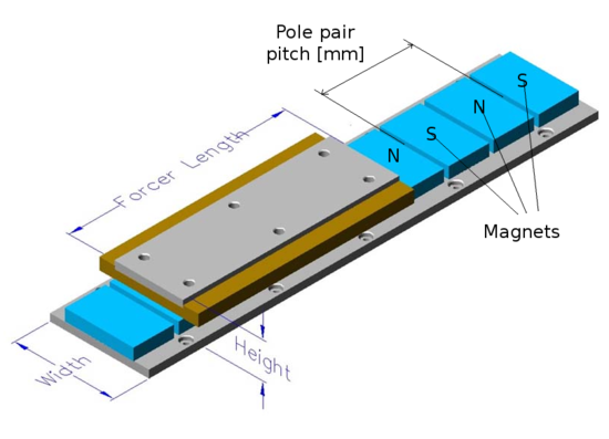
- Magnetic pole pair pitch (this equals 2x pole pitch)
- Forcer winding specifications:
- Maximum currents: continuous and peak
- Inductance and resistance
- Thermal time constant (optional but recommended)
Needed linear feedback device parameters:
- Resolution (lines or pulses per millimeter)
Setting parameters[edit | edit source]
In this step we convert the values so that motor can be driven from a servo drive. The drive is made to believe that the linear motor is rotary motor, so we need to figure out the equivalent rotary motor parameters.
This example works with Granity software. Follow your drive's setup guide for all parts except these:
- Set Motor typeMT as 3 phase AC or BLDC motor
- Set Pole countMPC to 2
- Set Feedback device resolutionFBR to a value calculated as: Lines per mm*Pole pair pitch. For example if we have a linear encoder with 100 pulses per millimeter and a linear motor with 50 mm pole pair pitch (25 mm pole pitch), we calculate FBR = 100*50 = 5000. Important: check whether encoder resolution is specified as pulses or cycles per mm OR counts per mm - if it's defined as counts per mm (after 4X decoding), then this value needs to be divided by 4 to get pulses per mm which is the correct input value format.
- Set Thermal time constantMTC according to your motor. If the value is unknown, it is recommended to start with low values such as 30 seconds as the forcer of linear motor may have very low time constant. MTC attempts to protect motor from overheating.
- Finally as usual, Invert feedback directionFBI parameter must be set properly to achieve proper configuration.
It's also a good idea to set Axis type & unitsAXT type to Linear and set Axis scaleAXS to same as pole pair pitch so velocities and distances calculated by Granity will be shown in correct scale.
| Granity always assumes that we’re setting up a rotary motor, and when choosing linear axis as AXT, it assumes it’s driven by rotary motor (leadscrew/belt/rack'n'pinion transmission). With linear motors, one should imagine words “pole pair” in place of “revolution” in all unit labels in Granity. I.e. when Granity says "mm per revolution" it means "mm per pole pair". |
Troubleshooting[edit | edit source]
If motor refuses to move beyond certain distance from the starting position, check the settings of MPC and FBR. If unsure, try adjusting FBR to higher/lower values (30%-50% steps or so) and see if the travel range increases or decreases.
EMI notice[edit | edit source]
Especially ironless linear motors are known to leak large amounts of electromagnetic interference due to open construction and lack of Faraday's cage. It may be necessary to use an Edge filter between the drive and motor to reduce the amount of EMI.


