Difference between revisions of "SimpleMotion V2 port"
| [checked revision] | [checked revision] |
| Line 39: | Line 39: | ||
|} | |} | ||
¹) STO1 and STO2 are controlling two independent [[Safe torque off]] methods. Both must be supplied 24V simultaneously to enable torque to the motor. | ¹) STO1 and STO2 are controlling two independent [[Safe torque off]] methods. Both must be supplied 24V simultaneously to enable torque to the motor. | ||
| − | {{ | + | {{damage|Even when RJ45 connector and cables are being used in Ethernet and SimpleMotion, these protocols are not electrically compatible. Never connect SimpleMotion device to Ethernet device.}} |
| + | {{damage|Don't use [http://en.wikipedia.org/wiki/Ethernet_crossover_cable crossover] cables in SimpleMotion V2 system}} | ||
[[Category:Setup guides]] | [[Category:Setup guides]] | ||
[[Category:Hardware]] | [[Category:Hardware]] | ||
[[Category:SimpleMotion]] | [[Category:SimpleMotion]] | ||
[[Category:Argon]] | [[Category:Argon]] | ||
Revision as of 23:49, 15 June 2013
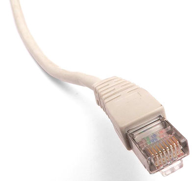
SimpleMotion V2 communication link and Argon drives use RJ45 connectors and cables as physical connection standard.
RJ45 is well known from Ethernet connectors and same cables may be used with SimpleMotion wiring.
Electrical properties
SimpleMotion V2 uses RS485 electrical serial communication standard for all data transfer. Some main benefits of using RS485 are:
- Multidrop buses possible (up to 32 devices in single serial link)
- High reliability due to differential signaling
- High data rates and long cable lengths possible
- Easy to interface even from smallest microcontrollers with UART
- Low wire count, only 2 signal wires + ground needed
- Bidirectional data transfer (receive & transmit) in one wire pair
As default SimpleMotion V2 uses 460800 BPS bitrate and can deliver over 10 000 motion commands per second.
Use as E-stop & Enable input
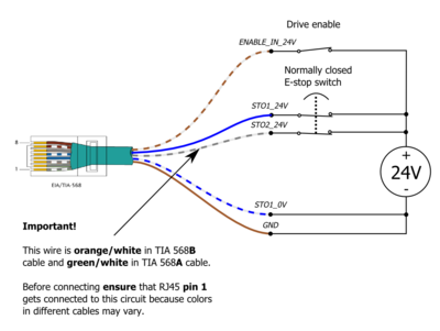
In Argon drive, the same connector acts also as emergencecy stop or Safe torque off input. User may connect a e-stop button directly at the end of device chain to gain reliable stopping mechanism for all linked devices.
Connector pinout
| Pin # | Signal name | Description | Electrical wiring |
|---|---|---|---|
| 1 | STO2_24V | STO input 2 | Supply 24VDC in this pin referenced to GND to disable STO2. ¹ |
| 2 | Reserved | Reserved for future use | Do not connect |
| 3 | RS485_A | RS485 signal A | RJ45 cable routes this between devices and SimpleMotion V2 USB adapter |
| 4 | STO1_24V | STO input 1 24V in | Supply 24VDC between STO1_24V and STO1_0V to disable STO1. STO1 inputs are floating and isolated from GND. ¹ |
| 5 | STO1_0V | STO input 1 0V in | |
| 6 | RS485_B | RS485 signal B | RJ45 cable routes this between devices and SimpleMotion V2 USB adapter |
| 7 | ENABLE_IN_24V | Drive enable control signal | Supply 24VDC in this pin referenced to GND to set drive in enabled state. |
| 8 | GND | Ground reference for: RS485, STO2 and ENABLE_IN | RJ45 cable routes this between devices and SimpleMotion V2 USB adapter. For enable & STO connect this to external 24V power supply ground. |
¹) STO1 and STO2 are controlling two independent Safe torque off methods. Both must be supplied 24V simultaneously to enable torque to the motor.
| Even when RJ45 connector and cables are being used in Ethernet and SimpleMotion, these protocols are not electrically compatible. Never connect SimpleMotion device to Ethernet device. |
| Don't use crossover cables in SimpleMotion V2 system |


