Difference between revisions of "About SimuCUBE"
| [checked revision] | [checked revision] |
m (→Links and miscellaneous notes) |
(→STM32F4 firmware files) |
||
| Line 188: | Line 188: | ||
The SimuCUBE has few pin headers for future upgrades and features. These are reserved until future notice. | The SimuCUBE has few pin headers for future upgrades and features. These are reserved until future notice. | ||
==Configuration files== | ==Configuration files== | ||
| − | ===STM32F4 firmware | + | ===STM32F4 firmware upgrade=== |
Please read the following guide, how to update the STM32F4 firmware. | Please read the following guide, how to update the STM32F4 firmware. | ||
| + | :Text/link here | ||
| + | |||
| + | ===STM32F4 firmware files=== | ||
{|class ="wikitable" | {|class ="wikitable" | ||
Revision as of 10:10, 5 April 2016
| This section is unfinished. Don't use until this notice is removed. |
External connectors
Legend
| Color |
|---|
| Supply pin |
| Input pin |
| Output pin |
Motor & E-stop connector
Pin 1 is the left-most.
| Pin number | Signal name | Usage |
|---|---|---|
| 1 | U / PH1 | Motor phase 1 |
| 2 | V / PH2 | Motor phase 2 |
| 3 | W / PH3 | Motor phase 3 |
| 4 | PH4 | Motor phase 4 |
| 5 | GND | Ground voltage (0 V) of the SimuCUBE |
| 6 | E-Stop / STO | External stop / Safe Torque Off input pin (active high) |
| 7 | +5 V | 5 V supply voltage. |
Motor position sensor connector
A, B, and C indicate the quadrature encoder differential signals.
| Pin # | Pin name | Electrical type (in most feedback device modes) |
|---|---|---|
| Shell | GND | Earth / 0 V |
| 1 | HALL_W | Hall sensor digital input W |
| 2 | HALL_V | Hall sensor digital input V |
| 3 | HALL_U | Hall sensor digital input U |
| 4 | GND | Encoder supply ground / 0 V |
| 5 | B- | Encoder differential input B- |
| 6 | B+ | Encoder differential input B+ |
| 7 | A- | Encoder differential input A- |
| 8 | A+ | Encoder differential input A+ |
| 9 | 5V_OUT | Encoder supply +5 V output |
| 10 | GND | Encoder supply ground / 0 V |
| 11 | GPI3 | IONI GPI3 input |
| 12 | GPI2 | IONI GPI2 input |
| 13 | GPI1 | IONI GPI1 input |
| 14 | C- | Encoder differential input C- |
| 15 | C+ | Encoder differential input C+ |
RJ45-1 (top-left)
Pin 1 is the right-most. These are active-low with an internal 3.3 kOhm pull-up resistor.
| Pin number | Signal name | Usage |
|---|---|---|
| 1 | Button 12 | |
| 2 | Button 7 | |
| 3 | Button 8 | |
| 4 | Button 9 | |
| 5 | Button 10 | |
| 6 | Button 6 | |
| 7 | Button 11 | |
| 8 | GND / 0 V |
RJ45-2 (bottom-left)
Pin 1 is the right-most. These are active-low with an internal 3.3 kOhm pull-up resistor.
| Pin number | Signal name | Usage |
|---|---|---|
| 1 | Button 3 | |
| 2 | Button 4 | |
| 3 | Button 2 | |
| 4 | Button 5 | |
| 5 | Button 13 | |
| 6 | Button 14 | |
| 7 | Button 15 | |
| 8 | GND / 0 V |
RJ45-3 (top-right)
Pin 1 is the left-most.
| Pin number | Signal name | Usage |
|---|---|---|
| 1 | Brake | ADC input for brake pedal |
| 2 | Throttle | ADC input for throttle pedal |
| 3 | ADC-14 | ADC input |
| 4 | 5V_OUT | +5 V supply |
| 5 | Clutch | ADC input for clutch pedal |
| 6 | ADC-7 | ADC input |
| 7 | CLK_OUT | |
| 8 | GND / 0 V |
RJ45-4 (bottom-right)
Pin 1 is the left-most.
| Pin number | Signal name | Usage |
|---|---|---|
| 1 | Button 16 | |
| 2 | ADC-13 | ADC input |
| 3 | ADC-3 | ADC input |
| 4 | 5V_OUT | +5 V supply |
| 5 | DAC-1 | |
| 6 | DAC-2 | |
| 7 | ADC-6 | ADC input |
| 8 | GND / 0 V |
USB Connectors
| Connector | Usage | Notes |
|---|---|---|
| USB-1 | USB connector for the HID | |
| USB-2 | USB connector for the IONI |
Wiring
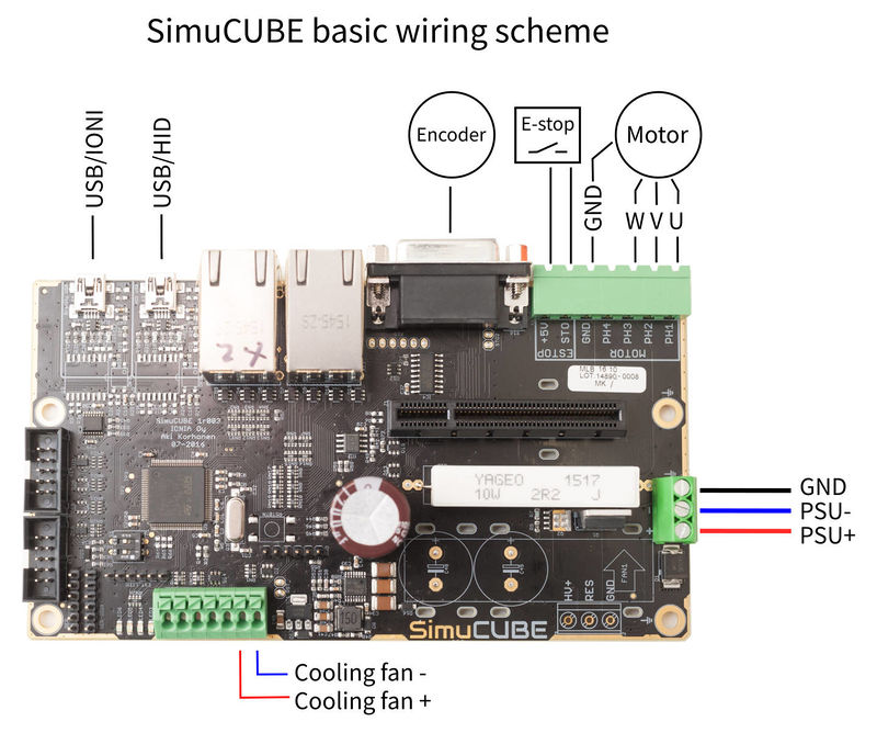
Basic wiring scheme

SimuCUBE basic wiring scheme. Please see the motor position sensor table for the DB15 connector pinout.
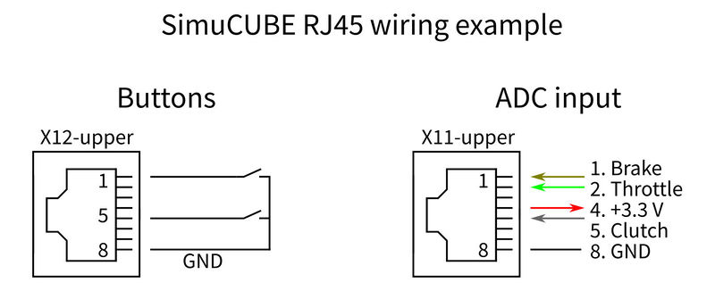
RJ45 connectors
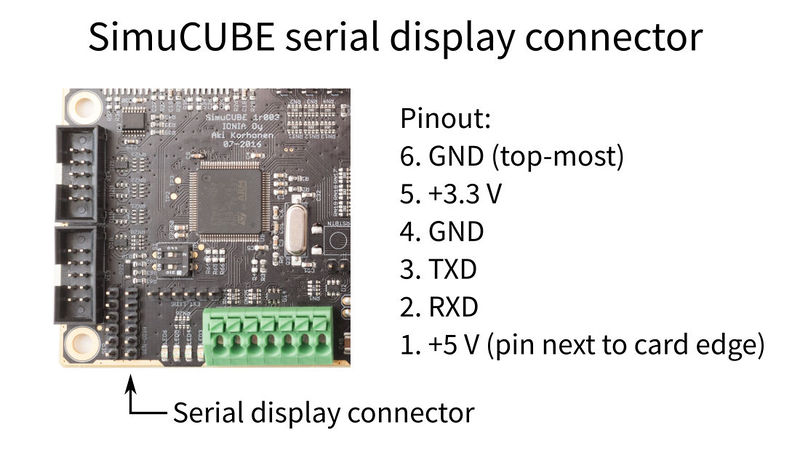
Serial display
Pin headers & other connectors
The SimuCUBE has few pin headers for future upgrades and features. These are reserved until future notice.
Configuration files
STM32F4 firmware upgrade
Please read the following guide, how to update the STM32F4 firmware.
- Text/link here
STM32F4 firmware files
| FW version | FW file | Description/changes |
|---|---|---|
IONI firmware
Read the following guide how to upgrade the IONI firmware:
The latest firmware can be found here:
Motor configuration files for Granity (.drc)
If you have a working configuration file for a specific motor, we would like to add it here.
| Motor name | Motor model | Notes | Configuration file | Contributor |
|---|---|---|---|---|
| Mige (small) | Mige 130ST-M10010 | 1 kW, 10 Nm (20 Nm peak) | file here someday | Granite Devices Inc. |
| Mige (large) | Mige 130ST-M15015 | 2.3 kW, 15 Nm (30 Nm peak) | file here someday | Granite Devices Inc. |
| Lenze | MCS12H15L | 1.6 kW, 11.4 Nm (29 Nm peak) | file here someday | Granite Devices Inc. |
Links and miscellaneous notes
Please read also these pages to get the best possible experience of SimuCUBE FFW system.


