Difference between revisions of "EMI suppression cores"
| [checked revision] | [checked revision] |
| Line 11: | Line 11: | ||
*Inductor cores | *Inductor cores | ||
*Iron powder cores | *Iron powder cores | ||
| − | + | *Most ferrite & iron powder cores look same. If unsure about material properties, its most safe to purchase new low to medium frequency cores. | |
| + | |||
| + | As example, take a look at [http://lairdtech.thomasnet.com/category/round-and-cylindrical-cores?&plpver=10 Laird broadband and low frequency cores]. | ||
==Where to find suitable cores== | ==Where to find suitable cores== | ||
Ferrite cores are available from most electronic part distributors such as: | Ferrite cores are available from most electronic part distributors such as: | ||
| Line 20: | Line 22: | ||
* Laird-Signal Integrity Products | * Laird-Signal Integrity Products | ||
* Fair-Rite | * Fair-Rite | ||
| − | ==Usage | + | ==Usage== |
| − | To solve an EMI problem its good to have selection of | + | ===Application=== |
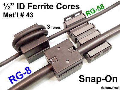
| + | [[File:Ferrite multiple turns.jpg|thumb|Turning cable 2-3 times through core or using multiple in series increases filtering performance.]] | ||
| + | Application tips: | ||
| + | *Make 2-3 turns of cable through one core to maximize it's effectiveness | ||
| + | *Place core close to interference source, not in the middle of the cable | ||
| + | ===With servo drives=== | ||
| + | To solve an EMI problem its good to have selection of cores that can be tried on different cables. Most typical placement for cores: | ||
| + | *Motor output cable (all motor wires through core but '''not''' earth conductor) | ||
| + | *High voltage power supply cable (+ and - leads through core) | ||
*USB adapter | *USB adapter | ||
| − | *CMD | + | *CMD & control I/O cables |
| − | *Encoder cable | + | *Encoder/feedback device cable |
| − | + | Note: don't run multiple different type of signals through single core. I.e. don't combine power supply and motor leads in one core. | |
| − | + | ||
| − | Note: don't run multiple | + | |
==See also== | ==See also== | ||
*[[Wikipedia:Ferrite bead]] | *[[Wikipedia:Ferrite bead]] | ||
[[Category:Troubleshooting]] | [[Category:Troubleshooting]] | ||
[[Category:Setup guides]] | [[Category:Setup guides]] | ||
Revision as of 21:04, 14 March 2013
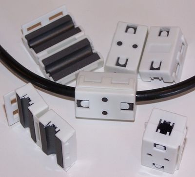
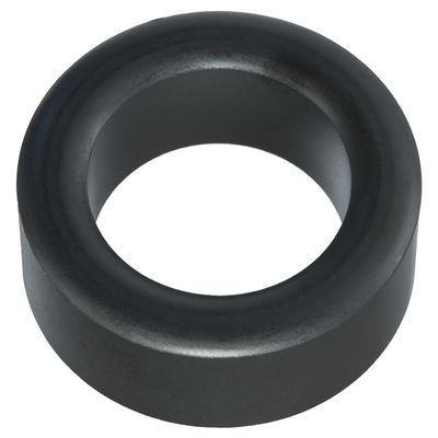
EMI suppression cores or ferrite cores are an efficient way to reduce high frequency interference from wiring. Running cables through a ferrite beads is a recommended solution attempt if signal reliability problems are encountered.
Contents
Selection
For motor control applications it is recommended to get low to medium frequency ferrite cores for maximum efficiency.
- Preferred types
- Core material designed for low to medium frequency bands (attenuation between 1-300 MHz)
- Large enough to fit cable multiple rounds through it
- Avoid (might make things worse)
- Core material designed for high frequency bands (above 300 MHz)
- Inductor cores
- Iron powder cores
- Most ferrite & iron powder cores look same. If unsure about material properties, its most safe to purchase new low to medium frequency cores.
As example, take a look at Laird broadband and low frequency cores.
Where to find suitable cores
Ferrite cores are available from most electronic part distributors such as:
- Digikey
- Mouser
- Farnell
Some popular ferrite core brands:
- Laird-Signal Integrity Products
- Fair-Rite
Usage
Application
Application tips:
- Make 2-3 turns of cable through one core to maximize it's effectiveness
- Place core close to interference source, not in the middle of the cable
With servo drives
To solve an EMI problem its good to have selection of cores that can be tried on different cables. Most typical placement for cores:
- Motor output cable (all motor wires through core but not earth conductor)
- High voltage power supply cable (+ and - leads through core)
- USB adapter
- CMD & control I/O cables
- Encoder/feedback device cable
Note: don't run multiple different type of signals through single core. I.e. don't combine power supply and motor leads in one core.


