Difference between revisions of "Argon EXT connector"
| [checked revision] | [checked revision] |
(→Simulated encoder output) |
(→Simulated encoder output) |
||
| Line 32: | Line 32: | ||
# Not in use, do not connect | # Not in use, do not connect | ||
| + | ;Wiring | ||
| + | As EXT connector pins are directly connected to microcontroller, they are very sensitive to ESD and damage by inproper loading. It is highly recommended to use optoisolator based buffer between the motion controller and EXT connector to prevent damaging devices in case of wiring error. | ||
| + | |||
| + | The suggested way is to use optocouplers with type H11L1 and circuit in order to achieve galvanic isolation and signal buffering at the same time. | ||
| + | |||
| + | {{picturebox|EXTisolator.png|caption=Encnoder simulator signal buffering with isolation. 5V-ISOLATED should be connected to motion controller's 5V supply (powering the optoisolators).}} | ||
| + | |||
| + | Suggested part types for isolation are: | ||
| + | *Optoisolators: H11L1 (support frequency up to 500 kHz) | ||
| + | *Resistors: 1 kOhm | ||
| + | *Capacitor (for opto 5V supply): 100nF 25V ceramic. Optionally also 10-100uF electrolytic in parallel. | ||
[[category:Argon features]] | [[category:Argon features]] | ||
Revision as of 13:02, 2 July 2015
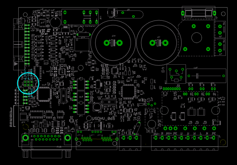
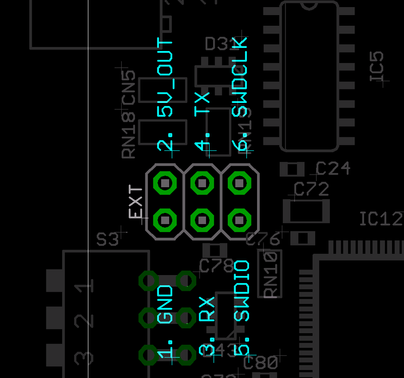
Argon (servo drive) has an internal 6 pin header that is directly connected to the I/O side user programmable STM32F205RBT6 microcontroller. EXT connector has several purposes:
- MCU debugging port (SWD)
- Extension board connector (5V power supply and I/O & UART to extension board)
- Simulated encoder output port (i.e. output resolver position in quadrature format)
| EXT connector is directly wired to microcontroller I/O pins without any protection devices (such as ESD clamp diodes, or resistors). Any misiring may cause permanent damage to the drive. |
| Damage caused through EXT connector is not covered by the warranty. |
Pinout
Simulated encoder output
From Argon firmware 2.0 version, the default function of EXT connector is an simulated encoder output. The pins will output quadrature signals to represent the position changes on feedback device (encoder, resolver etc).
- Features
- Output A,B,Z 3.3 volt signals
- Minimum output pulse length 2 µs (requirement for receiving device to accept count rate of 1 MHz)
- Output resolution is divided by 4 compared to the native resolution of the feedback device. I.e. single turn resolver will yield 512 encoder pulses per revolution (2048 counts per rev after 4X decoding).
- Limitations
- Output has lots of jitter (will look ugly on oscilloscope)
- Index pulse may have delay of 1ms or more delay from the real index pulse location. EXT index pulse should be used for homing at very low speeds only (speed less than 1000 of feedback device counts per second)
- No ESD protection, external buffer or protection circuit highly recommended
- Maximum output count rate 275 000 counts/s
- Pinout of encoder simulation
- GND
- 5V_OUT (leave unconnected if not needed)
- A
- B
- Z (index)
- Not in use, do not connect
- Wiring
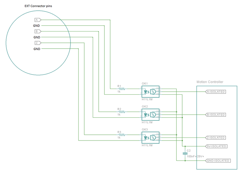
As EXT connector pins are directly connected to microcontroller, they are very sensitive to ESD and damage by inproper loading. It is highly recommended to use optoisolator based buffer between the motion controller and EXT connector to prevent damaging devices in case of wiring error.
The suggested way is to use optocouplers with type H11L1 and circuit in order to achieve galvanic isolation and signal buffering at the same time.

Encnoder simulator signal buffering with isolation. 5V-ISOLATED should be connected to motion controller's 5V supply (powering the optoisolators).
Suggested part types for isolation are:
- Optoisolators: H11L1 (support frequency up to 500 kHz)
- Resistors: 1 kOhm
- Capacitor (for opto 5V supply): 100nF 25V ceramic. Optionally also 10-100uF electrolytic in parallel.

