Difference between revisions of "Configuring cogging torque compensation"
| [checked revision] | [checked revision] |
(→Finding values) |
(→Finding values) |
||
| Line 21: | Line 21: | ||
Determining cogging torque frequency is straight forward. | Determining cogging torque frequency is straight forward. | ||
#Rotate unpowered motor by hand count the number of major "steps" or "cogs" per revolution | #Rotate unpowered motor by hand count the number of major "steps" or "cogs" per revolution | ||
| − | #Divide this number by motor poles and multiply by two. So equation is N=2*number_of_cogs/pole_count (same as {{param|MPC}}. | + | #Divide this number by motor poles and multiply by two. So equation is N=2*number_of_cogs/pole_count (same as {{param|MPC}}. |
| − | #The optimal TRF1 function is either Sin(Nx) or Cos(Nx). | + | #The optimal TRF1 function is either Sin(Nx) or Cos(Nx). For example, if motor has 8 poles, and we feel 12 cogs per revolution, the value of N becomes 2*12/8=3. So in this case we would use Sin(3x) or Cos(3x) function. |
{{warning|These methods are done on user's own risk. Remember that any malfunction in software or hardware may cause unexpectedly high torque.}} | {{warning|These methods are done on user's own risk. Remember that any malfunction in software or hardware may cause unexpectedly high torque.}} | ||
Revision as of 23:19, 2 November 2015
Cogging torque compensation feature in drive that aims to make motor torque production more uniform and ideal.
"Cogging torque of electrical motors is the torque due to the interaction between the permanent magnets of the rotor and the stator slots of a Permanent Magnet (PM) machine. It is also known as detent or ‘no-current’ torque. This torque is position dependent and its periodicity per revolution depends on the number of magnetic poles and the number of teeth on the stator.”
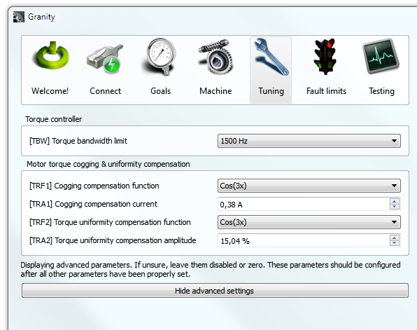
This can be compensated by modulating motor current to counter the motor cogging. In some Granite Devices drives (IONI Pro family on the time of writing) there are options to adjust compensation current by few parameters.
Configuration
Parameters
Static no-current cogging compensation is done by summing a fixed amplitude waveform on the torque setpoint. The default waveforms are sinusoidal where phase angle of sine is driven by motor angle.
- Cogging compensation functionTRF1 - selects the function of compensator
- Cogging compensation currentTRA1 - adjusts the amplitude of summed torque command
Dynamic torque ripple compensation helps to reduce non-uniform torque when non-zero current is being driven. The method of operation is same, except this time setpoint amplitude is modulated by scaling of torque setpoint.
- Torque ripple compensation functionTRF2 - selects the function of compensator
- Torque ripple compensation amplitudeTRA2 - adjust the modulation depth of compensator
Finding values
The first task is to determine the frequency of imperfections so we know which functions to start experimenting.
Determining cogging torque frequency is straight forward.
- Rotate unpowered motor by hand count the number of major "steps" or "cogs" per revolution
- Divide this number by motor poles and multiply by two. So equation is N=2*number_of_cogs/pole_count (same as Pole countMPC.
- The optimal TRF1 function is either Sin(Nx) or Cos(Nx). For example, if motor has 8 poles, and we feel 12 cogs per revolution, the value of N becomes 2*12/8=3. So in this case we would use Sin(3x) or Cos(3x) function.
| These methods are done on user's own risk. Remember that any malfunction in software or hardware may cause unexpectedly high torque. |
As the frequency is known, we proceed choosing the correct function and amplitude setting:
- Set drive in torque mode and enable it without any setpoint
- Start with Sin(Nx) function and try different TRA2 values (positive and negative, varying magnitudes). On each TRA2 value, try rotating motor by hand and identify the lowest cogging setting.
- Repeat the last step but this time with Cos(Nx) function.
- Choose the settings that yielded the lowest cogging
Perform the above procedure first for cogging torque, and then for ripple if necessary. However, in the ripple settings (TRF2 and TRA2), the test & comparison should be conducted when torque setpoint is set to a constant non-zero value (i.e. using Target setpoint 1TSP1 and Set Abs button. In this case, motor should be held still and rotated by hand to determine the lowest ripple settings.
| Beware of handling motor when torque setpoint is given. Always start with very low setpoint values to avoid injury or damage. Always keep emergency stopping method rapidly accessible. |
