Difference between revisions of "Intensify Nx50 setup guide"
From Granite Devices Knowledge Wiki
| [checked revision] | [checked revision] |
(→Wiring) |
(→Wiring) |
||
| Line 4: | Line 4: | ||
==Wiring== | ==Wiring== | ||
===CMD connector=== | ===CMD connector=== | ||
| − | CMD connector is a 10 pin flat ribbon cable connector with 0.1"/2.54 mm pin pitch and a polarity key. | + | CMD connector is the user side I/O of the driver. This connector contains the control and feedback signals. All signal lines of the port are ESD protected by dedicated suppressors. |
| + | |||
| + | Mating connector type is a 10 pin flat ribbon cable connector with 0.1"/2.54 mm pin pitch and a polarity key. See spec sheet of compatible connector [[Media:idc10pin_connector.pdf|here]]. | ||
| + | ===CMD pin-out=== | ||
{| class="wikitable" | {| class="wikitable" | ||
|- | |- | ||
| Line 29: | Line 32: | ||
| 10 || GND|| Power & digital ground | | 10 || GND|| Power & digital ground | ||
|} | |} | ||
| − | ===Differential signals=== | + | ===Digital signals=== |
| + | All digital signals (PULSE & ENABLE) are referenced to GND and applicable voltage levels are: | ||
| + | {| class="wikitable" | ||
| + | |- | ||
| + | ! State !! Voltage range | ||
| + | |- | ||
| + | | Logic low|| -0.3 .. 0.6V | ||
| + | |- | ||
| + | | Logic high|| 3.0 - 7.0 V | ||
| + | |} | ||
| + | ===Differential analog signals=== | ||
| + | Analog input & output signals support differential signaling to cancel noise and ground loop induced error. | ||
==Connecting parallel== | ==Connecting parallel== | ||
Revision as of 19:53, 13 February 2013

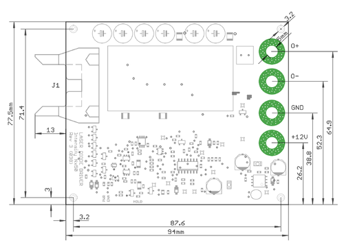
Intensify Nx50 PCB from top side
This is the intallation & user guide for the Intensify Nx50 laser diode driver. Read it through before operating the device.
Contents
Overview
Wiring
CMD connector
CMD connector is the user side I/O of the driver. This connector contains the control and feedback signals. All signal lines of the port are ESD protected by dedicated suppressors.
Mating connector type is a 10 pin flat ribbon cable connector with 0.1"/2.54 mm pin pitch and a polarity key. See spec sheet of compatible connector here.
CMD pin-out
| Header text | Header text | Header text |
|---|---|---|
| 1 | PULSE | Pulse control. When low, output low current and when high, output setpoint current. |
| 2 | GNDA | Analog ground |
| 3 | IMON+ | Current monitor positive output (differential) |
| 4 | IMON- | Current monitor negative output (differential) |
| 5 | VMON+ | Voltage monitor positive output (differential) |
| 6 | VMON- | Voltage monitor negative output (differential) |
| 7 | ISET+ | Current setpoint positive input (differential) |
| 8 | ISET- | Current setpoint negateive input (differential) |
| 9 | ENABLE | Enable input. When low, output enabled and high or open, output disabled. |
| 10 | GND | Power & digital ground |
Digital signals
All digital signals (PULSE & ENABLE) are referenced to GND and applicable voltage levels are:
| State | Voltage range |
|---|---|
| Logic low | -0.3 .. 0.6V |
| Logic high | 3.0 - 7.0 V |
Differential analog signals
Analog input & output signals support differential signaling to cancel noise and ground loop induced error.