Difference between revisions of "Intensify Nx50 setup guide"
| [checked revision] | [checked revision] |
| Line 42: | Line 42: | ||
| Logic high|| 3.0 - 7.0 V | | Logic high|| 3.0 - 7.0 V | ||
|} | |} | ||
| − | ==== | + | ====Analog signals==== |
Analog input & output signals support [[differential signaling]] to cancel noise and ground loop induced error. These are designed to be compatible with another differential source as well as single ended systems. | Analog input & output signals support [[differential signaling]] to cancel noise and ground loop induced error. These are designed to be compatible with another differential source as well as single ended systems. | ||
| − | Connection to differential 0-10V analog I/O: | + | Connection to '''differential''' 0-10V analog I/O: |
{| class="wikitable" | {| class="wikitable" | ||
|- | |- | ||
| Line 64: | Line 64: | ||
| Ground || GND | | Ground || GND | ||
|} | |} | ||
| − | Connecting to single ended 0-10V analog I/O. Assuming that I/O is referenced to Ground. | + | Connecting to '''single ended''' 0-10V analog I/O. Assuming that I/O is referenced to Ground. |
{| class="wikitable" | {| class="wikitable" | ||
|- | |- | ||
| Line 84: | Line 84: | ||
|} | |} | ||
===Power=== | ===Power=== | ||
| − | A regulated 12VDC power supply should be connected to hole terminals labeled GND and +12V. Required power is nearly directly proportional to output power plus losses. | + | A regulated 12VDC power supply should be connected to hole terminals labeled '''GND''' and '''+12V'''. Required power is nearly directly proportional to output power plus losses. |
For example outputting 40A to 2.0V diode equals output power of 80W. With losses the needed power is about 85-90W which equals 7.0-7.5A @ 12V. | For example outputting 40A to 2.0V diode equals output power of 80W. With losses the needed power is about 85-90W which equals 7.0-7.5A @ 12V. | ||
===Laser diode=== | ===Laser diode=== | ||
| − | Laser diode is connected to hole terminals labeled O+ and O-. O+ goes to LD anode and 0- to cathode. | + | Laser diode is connected to hole terminals labeled '''O+''' and '''O-'''. O+ goes to LD anode and 0- to cathode. |
==Connecting parallel== | ==Connecting parallel== | ||
==Usage== | ==Usage== | ||
Revision as of 20:50, 13 February 2013

This is the intallation & user guide for the Intensify Nx50 laser diode driver. Read it through before operating the device.
Contents
Overview
Wiring
CMD connector
CMD connector is the user side I/O of the driver. This connector contains the control and feedback signals. All signal lines of the port are ESD protected by dedicated suppressors.
Mating connector type is a 10 pin flat ribbon cable connector with 0.1"/2.54 mm pin pitch and a polarity key. See spec sheet of compatible connector here.
CMD pin-out
| Header text | Header text | Header text |
|---|---|---|
| 1 | PULSE | Pulse control. When low, output low current and when high, output setpoint current. |
| 2 | GNDA | Analog ground |
| 3 | IMON+ | Current monitor positive output (differential) |
| 4 | IMON- | Current monitor negative output (differential) |
| 5 | VMON+ | Voltage monitor positive output (differential) |
| 6 | VMON- | Voltage monitor negative output (differential) |
| 7 | ISET+ | Current setpoint positive input (differential) |
| 8 | ISET- | Current setpoint negateive input (differential) |
| 9 | ENABLE | Enable input. When low, output enabled and high or open, output disabled. |
| 10 | GND | Power & digital ground |
Digital signals
All digital signals (PULSE & ENABLE) are referenced to GND and applicable voltage levels are:
| State | Voltage range |
|---|---|
| Logic low | -0.3 .. 0.6V |
| Logic high | 3.0 - 7.0 V |
Analog signals
Analog input & output signals support differential signaling to cancel noise and ground loop induced error. These are designed to be compatible with another differential source as well as single ended systems.
Connection to differential 0-10V analog I/O:
| Controller | CMD signal |
|---|---|
| Analog in 1 + | IMON+ |
| Analog in 1 - | IMON- |
| Analog in 2 + | VMON+ |
| Analog in 2 - | VMON- |
| Analog out 1 + | ISET+ |
| Analog out 1 - | ISET- |
| Ground | GND |
Connecting to single ended 0-10V analog I/O. Assuming that I/O is referenced to Ground.
| Controller | CMD signal |
|---|---|
| Analog in 1 | IMON+ |
| Ground | IMON- |
| Analog in 2 | VMON+ |
| Ground | VMON- |
| Analog out 1 | ISET+ |
| Ground | ISET- |
| Ground | GND |
Power
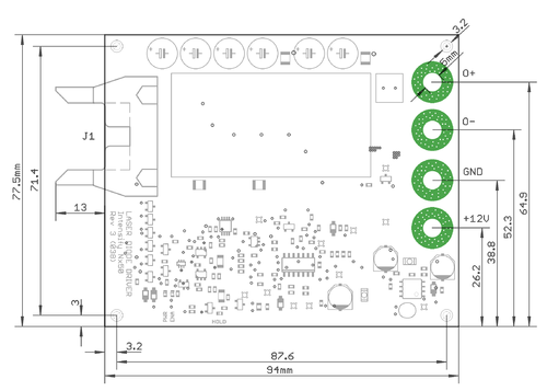
A regulated 12VDC power supply should be connected to hole terminals labeled GND and +12V. Required power is nearly directly proportional to output power plus losses.
For example outputting 40A to 2.0V diode equals output power of 80W. With losses the needed power is about 85-90W which equals 7.0-7.5A @ 12V.
Laser diode
Laser diode is connected to hole terminals labeled O+ and O-. O+ goes to LD anode and 0- to cathode.