About SimuCUBE
| This section is unfinished. Don't use until this notice is removed. |
Contents
External connectors
Legend
| Color |
|---|
| Supply pin |
| Input pin |
| Output pin |
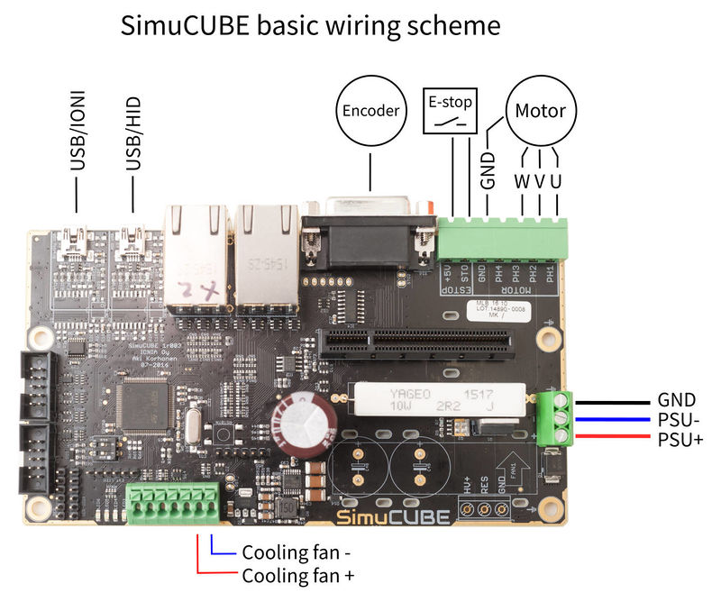
Motor & E-stop connector
Pin 1 is the left-most.
| Pin number | Signal name | Usage |
|---|---|---|
| 1 | U / PH1 | Motor phase 1 |
| 2 | V / PH2 | Motor phase 2 |
| 3 | W / PH3 | Motor phase 3 |
| 4 | PH4 | Motor phase 4 |
| 5 | GND | Ground voltage (0 V) of the SimuCUBE |
| 6 | E-Stop / STO | External stop / Safe Torque Off input pin (active high) |
| 7 | +5 V | 5 V supply voltage. |
Motor position sensor connector
A, B, and C indicate the quadrature encoder differential signals.
| Pin # | Pin name | Electrical type (in most feedback device modes) |
|---|---|---|
| Shell | GND | Earth / 0 V |
| 1 | HALL_W | Hall sensor digital input W |
| 2 | HALL_V | Hall sensor digital input V |
| 3 | HALL_U | Hall sensor digital input U |
| 4 | GND | Encoder supply ground / 0 V |
| 5 | B- | Encoder differential input B- |
| 6 | B+ | Encoder differential input B+ |
| 7 | A- | Encoder differential input A- |
| 8 | A+ | Encoder differential input A+ |
| 9 | 5V_OUT | Encoder supply +5 V output |
| 10 | GND | Encoder supply ground / 0 V |
| 11 | GPI3 | IONI GPI3 input |
| 12 | GPI2 | IONI GPI2 input |
| 13 | GPI1 | IONI GPI1 input |
| 14 | C- | Encoder differential input C- |
| 15 | C+ | Encoder differential input C+ |
RJ45-1 (top-left)
Pin 1 is the right-most. These are active-low with an internal 3.3 kOhm pull-up resistor.
| Pin number | Signal name | Usage |
|---|---|---|
| 1 | Button 12 | |
| 2 | Button 7 | |
| 3 | Button 8 | |
| 4 | Button 9 | |
| 5 | Button 10 | |
| 6 | Button 6 | |
| 7 | Button 11 | |
| 8 | GND / 0 V |
RJ45-2 (bottom-left)
Pin 1 is the right-most. These are active-low with an internal 3.3 kOhm pull-up resistor.
| Pin number | Signal name | Usage |
|---|---|---|
| 1 | Button 3 | |
| 2 | Button 4 | |
| 3 | Button 2 | |
| 4 | Button 5 | |
| 5 | Button 13 | |
| 6 | Button 14 | |
| 7 | Button 15 | |
| 8 | GND / 0 V |
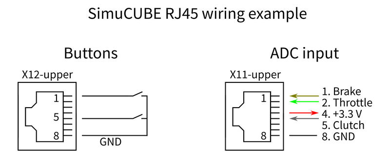
RJ45-3 (top-right)
Pin 1 is the left-most.
| Pin number | Signal name | Usage |
|---|---|---|
| 1 | Brake | ADC input for brake pedal |
| 2 | Throttle | ADC input for throttle pedal |
| 3 | ADC-14 | ADC input |
| 4 | 5V_OUT | +5 V supply |
| 5 | Clutch | ADC input for clutch pedal |
| 6 | ADC-7 | ADC input |
| 7 | CLK_OUT | |
| 8 | GND / 0 V |
RJ45-4 (bottom-right)
Pin 1 is the left-most.
| Pin number | Signal name | Usage |
|---|---|---|
| 1 | Button 16 | |
| 2 | ADC-13 | ADC input |
| 3 | ADC-3 | ADC input |
| 4 | 5V_OUT | +5 V supply |
| 5 | DAC-1 | |
| 6 | DAC-2 | |
| 7 | ADC-6 | ADC input |
| 8 | GND / 0 V |
USB Connectors
| Connector | Usage | Notes |
|---|---|---|
| USB-1 | USB connector for the HID | |
| USB-2 | USB connector for the IONI |
Wiring
In no event the Product Information or parts hereof shall be regarded as guarantee of conditions or characteristics. The Product Information or any part thereof may also not be regarded as a warranty of any kind. No liability of any kind shall be assumed by Author with respect to Product Information or any use made by you thereof, nor shall Author indemnify you against or be liable for any third party claims with respect to such information or any use thereof.
As content of this Wiki may be edited by user community, Granite Devices Oy or it's affiliates do not take any responsibility of the contents of this Wiki. Use information at your own risk. However, Granite Devices staff attempts to review all changes made to this Wiki and keep information trustworthy.
Without written consent, Granite Devices' Products or Intellectual Property shall not be used in situations or installations where living beings, material property, or immaterial property could be harmed by the operation, features or failures of Product. Products may only be used in a way where hazards like moving parts, electric shock, laser radiation, or fire can't be realized even if the content of this Wiki would suggest otherwise.


