Difference between revisions of "Analog setpoint"
| [unchecked revision] | [checked revision] |
(Created page with "Analog reference is one of [[Reference signal|reference signal] types used in motion control. The most typical reference voltage range is +/-10V where * -10V equals the most...") |
(→Differential signaling) |
||
| (14 intermediate revisions by 3 users not shown) | |||
| Line 1: | Line 1: | ||
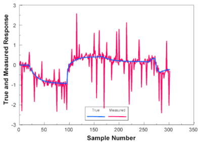
| − | Analog reference is one of [[ | + | [[File:Noise1.gif|thumb|Analog reference signal is ideally clean and precise (blue). However, in problematic cases [[Electromagnetic interference|electromagnetic interference]] is coupled to the signal (red) causing inaccuracies like noise and offset error/drifting.]] |
| + | Analog setpoint is one of [[setpoint signal]] types used in motion control. | ||
| − | The most typical | + | The most typical setpoint voltage range is +/-10V where |
| − | * -10V equals the most negative | + | * -10V equals the most negative setpoint (-100%) |
| − | * 0V equals zero | + | * 0V equals zero setpoint |
| − | * 10V equals most positive | + | * 10V equals most positive setpoint (+100%) |
* Any value between is interpolated linearly | * Any value between is interpolated linearly | ||
| − | Another common voltage range is 0..5V where | + | Another common voltage range is 0..5V where zero setpoint may be at 2.5 VDC (bias voltage). |
| + | |||
| + | ==Differential signaling== | ||
| + | Analog setpoint input in target device is typically differential. Differential input requires 3 wires from source device: | ||
| + | * Positive input | ||
| + | * Negative input | ||
| + | * Ground | ||
| + | The actual setpoint value will be calculated from the differential of positive and negative inputs. This eliminates error from ground currents and also reduces sensitivity to EMI noise. | ||
| + | {{tip|In typical servo drive, there are ANAIN+ and ANAIN- pins. Setpoint voltage is measured from the difference of voltage potentials between ANAIN+ and ANAIN-. Both ANAIN inputs must always lie within +/-12V from GND (meaning that [[controller]]'s zero voltage reference, i.e. GND must be connected to the GND if drive to prevent voltage potentials from floating.}} | ||
| + | |||
| + | [http://en.wikipedia.org/wiki/Differential_signaling Differential signaling on wikipedia] | ||
| + | |||
==Example== | ==Example== | ||
| − | Lets assume +/-10V is used as torque | + | Lets assume +/-10V is used as torque setpoint in VSD drive. In this case 0V equals no torque, and 10V equals 100% of peak torque configured in the drive, 5V equals 50% torque etc. |
| + | |||
| + | Peak torque can be configured to drive with [[GDtool]] as peak current limit. Torque and current are directly proportional, so torque setpoint is also a current setpoint. | ||
| + | [[Category:Signals]] | ||
| + | [[Category:Glossary]] | ||
Latest revision as of 12:23, 15 May 2015

Analog setpoint is one of setpoint signal types used in motion control.
The most typical setpoint voltage range is +/-10V where
- -10V equals the most negative setpoint (-100%)
- 0V equals zero setpoint
- 10V equals most positive setpoint (+100%)
- Any value between is interpolated linearly
Another common voltage range is 0..5V where zero setpoint may be at 2.5 VDC (bias voltage).
Differential signaling[edit | edit source]
Analog setpoint input in target device is typically differential. Differential input requires 3 wires from source device:
- Positive input
- Negative input
- Ground
The actual setpoint value will be calculated from the differential of positive and negative inputs. This eliminates error from ground currents and also reduces sensitivity to EMI noise.
| In typical servo drive, there are ANAIN+ and ANAIN- pins. Setpoint voltage is measured from the difference of voltage potentials between ANAIN+ and ANAIN-. Both ANAIN inputs must always lie within +/-12V from GND (meaning that controller's zero voltage reference, i.e. GND must be connected to the GND if drive to prevent voltage potentials from floating. |
Differential signaling on wikipedia
Example[edit | edit source]
Lets assume +/-10V is used as torque setpoint in VSD drive. In this case 0V equals no torque, and 10V equals 100% of peak torque configured in the drive, 5V equals 50% torque etc.
Peak torque can be configured to drive with GDtool as peak current limit. Torque and current are directly proportional, so torque setpoint is also a current setpoint.