Connecting motor to SimuCUBE
Connecting motor to SimuCUBE involves wiring motor power and Feedback device (encoder) to the corresponding connectors. This page instructs making these connections properly.

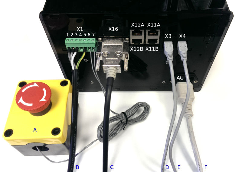
Cabling of SimuCUBE.
- X1 - 7 pin terminal for motor power and E-stop
- X16 - Motor feedback device/encoder input
- X3 - USB connector (HID/game controller)
- X4 - USB connector (Granity/IONI configuration)
- AC - 110-240 VAC power inlet
- X12A & X12B - External button inputs (optional)
- X13A - Pedal inputs (optional)
- X11B - External analog inputs (optional)
- A - E-Stop (normally closed/conducting switch)
- B - Motor power cable
- C - Motor encoder cable
- D - USB to PC (HID/game controller)
- E - USB to PC (Granity/IONI configuration)
- F - AC power cord.
Contents
Motor power
Motor power cable consists windings and the protective earth conductors. In 3 phase AC servo motor there are four conductors and they should be connected to X1 terminal block according to the table below:
Motor feedback device
Feedback device (in this case position sensor, usually encoder) need to be connected to SimuCUBE X16 input. X16 connector type on SimuCUBE is D-Sub 15 pin female with two pin rows, so the mating part is D-Sub 15 pin male connector with two pin rows.
Case A: pre-made encoder cable
If you have a motor that comes with pre-made encoder cable with SimuCUBE, IONI or ARGON compatible connector, then simply plug this connector to SimuCUBE X16.
| Pin number | Signal name | Function | Usage |
|---|---|---|---|
| 1 | U / PH1 | Motor phase 1 | AC servo motor phase U |
| 2 | V / PH2 | Motor phase 2 | AC servo motor phase V |
| 3 | W / PH3 | Motor phase 3 | AC servo motor phase W |
| 4 | PH4 | Motor phase 4 | Used only with 2-phase stepping motor |
| 5 | GND | Motor protective earth conductor | The yellow/green wire |
| 6 | E-Stop / STO | E-Stop switch input | Normall closed (conducting) E-Stop switch goes between pins 6 and 7 |
| 7 | +5 V | 5 VDC output (max 100 mA) |
Case B: make encoder connection
If motor encoder cable comes with bare wire ends, or with incompatible connector, then soldering a D-Sub connector with SimuCUBE pin-out is necessary. A, B, and C indicate the quadrature encoder differential signals. C channel is often also denoted as Z, Index or IDX.
| Pin # | Pin name | Electrical type (in most feedback device modes) |
|---|---|---|
| Shell | GND | Earth / 0 V |
| 1 | HALL_W | Hall sensor digital input W (optional) |
| 2 | HALL_V | Hall sensor digital input V (optional) |
| 3 | HALL_U | Hall sensor digital input U (optional) |
| 4 | GND | Encoder supply ground / 0 V |
| 5 | B- | Encoder differential input B- |
| 6 | B+ | Encoder differential input B+ |
| 7 | A- | Encoder differential input A- |
| 8 | A+ | Encoder differential input A+ |
| 9 | 5V_OUT | Encoder supply +5 V output |
| 10 | GND | Encoder supply ground / 0 V |
| 11 | GPI3 | no connection |
| 12 | GPI2 | no connection |
| 13 | GPI1 | no connection |
| 14 | C- | Encoder differential input C- |
| 15 | C+ | Encoder differential input C+ |
Legend
Colors codes in the pin-out tables:
| Color |
|---|
| Supply pin |
| Input pin |
| Output pin |
In no event the Product Information or parts hereof shall be regarded as guarantee of conditions or characteristics. The Product Information or any part thereof may also not be regarded as a warranty of any kind. No liability of any kind shall be assumed by Author with respect to Product Information or any use made by you thereof, nor shall Author indemnify you against or be liable for any third party claims with respect to such information or any use thereof.
As content of this Wiki may be edited by user community, Granite Devices Oy or it's affiliates do not take any responsibility of the contents of this Wiki. Use information at your own risk. However, Granite Devices staff attempts to review all changes made to this Wiki and keep information trustworthy.
Without written consent, Granite Devices' Products or Intellectual Property shall not be used in situations or installations where living beings, material property, or immaterial property could be harmed by the operation, features or failures of Product. Products may only be used in a way where hazards like moving parts, electric shock, laser radiation, or fire can't be realized even if the content of this Wiki would suggest otherwise.